
D08.50-A031-79
Thermal management, block diagram |
A1 | Instrument cluster | N24/6 | Direct current charge connection unit | |
A9/6 | Electric refrigerant compressor | N33/16 | High-voltage PTC heater control unit | |
A79/1 | Electric machine 1 | N33/17 | Battery heater control unit | |
A79/3 | Power electronics control unit | N73/8 | Electronic ignition lock (EZS) control unit | |
B11/6 | Low temperature coolant circuit temperature sensor 1 | N82/2 | Battery management system control unit | |
B11/7 | Low temperature coolant circuit 2 temperature sensor | N83/3 | DC/DC converter control unit | |
B94/2 | Electric machine temperature sensor | N83/15 | Alternating current charger for high-voltage battery | |
B161/1 | Cooler pressure and temperature sensor | N127 | Drivetrain control unit | |
B161/2 | Condenser pressure and temperature sensor | Y16/9 | Condensation prevention switchover valve | |
B183/11 | High-voltage battery temperature sensor 1 | Y19/19 | High-voltage battery cooling system evaporator shutoff valve | |
B183/12 | High-voltage battery temperature sensor 2 | Y125/5 | High-voltage battery cooling system switchover valve | |
B183/13 | High-voltage battery temperature sensor 3 | Y140/1 | Expansion valve | |
B183/14 | High-voltage battery temperature sensor 4 (with code E4T (High-voltage battery (47 kWh))) | CAN B | Interior CAN | |
G1/31 | High-voltage battery 1 | CAN BAT | Battery management system CAN | |
G1/32 | High-voltage battery 2 | CAN ED | Electric drive system CAN | |
G1/33 | High-voltage battery 3 | CAN HMI | User interface CAN | |
G1/34 | High-voltage battery 4 (with code E4T (High-voltage battery (47 kWh))) | CAN L | Hybrid CAN | |
M4/14 | Cooler fan | CAN PER | Peripherals CAN | |
M13/4 | Circulation pump | Flex E | Chassis FlexRay | |
M75/16 | Low-temperature circuit coolant circulation pump 1 | LIN B8 | Climate control LIN | |
M75/17 | Low-temperature circuit coolant circulation pump 2 | LIN C3 | Drivetrain LIN | |
N10 | SAM control unit | O | Optional | |
N22/2 | Automatic air conditioning control and operating unit | S | Default |
D20.00-A004-79
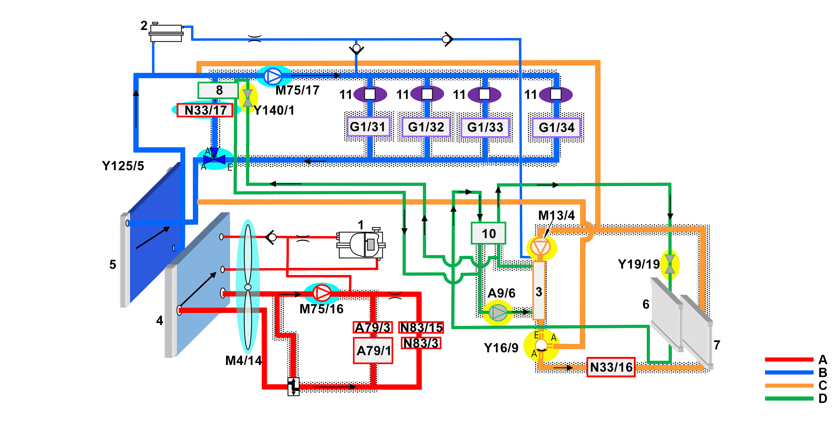
Thermal management, schematic diagram |
1 | Low-temperature circuit 1 expansion reservoir | M4/14 | Cooler fan | |
2 | Low-temperature circuit 2 expansion reservoir | M13/4 | Circulation pump | |
3 | Condenser | M75/16 | Low-temperature circuit coolant circulation pump 1 | |
4 | Low-temperature circuit 1 cooler | M75/17 | Low-temperature circuit coolant circulation pump 2 | |
5 | Low-temperature circuit 2 cooler | N33/16 | High-voltage PTC heater control unit | |
6 | Evaporator (vehicle interior) | N33/17 | Battery heater control unit | |
7 | Heating system heat exchanger | N83/3 | DC/DC converter control unit | |
8 | Evaporator/heat exchanger | N83/15 | Alternating current charger for high-voltage battery | |
10 | Inner heat exchanger | Y16/9 | Condensation prevention switchover valve | |
11 | Control valve | Y19/19 | High-voltage battery cooling system evaporator shutoff valve | |
A9/6 | Electric refrigerant compressor | Y125/5 | High-voltage battery cooling system switchover valve | |
A79/1 | Electric machine 1 | Y140/1 | Expansion valve | |
A79/3 | Power electronics control unit | A | Low-temperature circuit 1 | |
G1/31 | High-voltage battery 1 | B | Low-temperature circuit 2 | |
G1/32 | High-voltage battery 2 | C | Heating circuit | |
G1/33 | High-voltage battery 3 | D | Refrigerant circuit | |
G1/34 | High-voltage battery 4 (with code E4T (High-voltage battery (47 kWh))) |
High-voltage on-board electrical system cooling function requirements, general
Circuit 30
Function sequence for the high voltage on-board electrical system cooling
The function sequence is described in the following steps:
Thermal management, general
Thermal management function
Structure
Cooling of electric machine 1 and high voltage components (low-temperature circuit 1)
Cooling of high-voltage batteries (low-temperature circuit 2)
Thermal management, general
Waste heat is generated as a by-product during the conversion of electrical energy into kinetic energy and the conversion of the different voltages. To dissipate this waste heat, the electric drive has an intelligent, water-based thermal management.
The operating temperature of the high-voltage batteries and the electric machine 1 (A79/1) must be in a specific range in order to ensure that the charging capacity, the number of charging cycles, and the life expectancy of the high-voltage batteries or operation of high voltage components are optimized and secured. The high-voltage batteries and electric machine 1 are therefore part of the separate low-temperature coolant circuits:
Low-temperature circuit 1
Cooling of the high voltage components and electric machine 1
Low-temperature circuit 2
Cooling and/or temperature control of high-voltage batteries
During vehicle operation and charge mode, the low-temperature circuit 1 cools the electric machine 1, the power electronics control unit (A79/3), and the high voltage components (AC charger for high-voltage battery (N83/15) and the DC/DC converter control unit (N83/3)) and protects against damage due to overheating.
The high-voltage batteries are cooled and/or brought to the desired temperature via low-temperature circuit 2.
The generated heat of the high-voltage batteries is, if necessary, dissipated according to the heat pump principle to the refrigerant circuit of the air conditioning system and also routed via the water-cooled condenser to the heating circuit and used for heating the vehicle interior. The energy consumption from the high-voltage batteries for heating the vehicle interior is thus reduced and the energy balance of the high-voltage on-board electrical system is thereby preserved. In the case of a sufficient temperature difference between the outside air and the high-voltage batteries, this is - if necessary - also cooled via the front radiator.
The low-temperature circuit 1 coolant circulation pump (M75/16) for the electric machine 1 and the low-temperature circuit 2 coolant circulation pump (M75/17) for the high-voltage batteries are permanently activated by the powertrain control unit (N127) during vehicle operation. The battery management system control unit (N82/2) evaluates the temperature of the high-voltage batteries via the temperature sensors of the high-voltage batteries and transmits this status to the powertrain control unit.
The temperature sensors of electric machine 1, the high-voltage batteries and the coolant circuits check the operating temperature of the high-voltage on-board electrical system to ensure an optimal operating temperature and the longevity of the components. At low ambient temperatures, the coolant in low-temperature circuit 2 is heated via the battery heater control unit (N33/17) in order to reach the operating temperature of the high-voltage batteries.
The generated heat of the high-voltage batteries is also dissipated on the heating circuit if necessary and used for the heating of the vehicle interior. As a result, the energy consumption from the high-voltage batteries is reduced by heating the vehicle interior and thus the range of the electric vehicle is increased.
Detailed information on the air conditioning refrigerant circuit and on the vehicle interior heating circuit is contained in the separate function description "Klimatisierung Elektrofahrzeug Funktion" (Climate control electric vehicle function).
Detailed information on the high-voltage battery heating can be found in the separate function description "High-voltage on-board electrical system function".
Thermal management function
Compared to the combustion vehicle, the thermal management system in the electric vehicle has numerous additional functions:
Cooling of electric powertrain and electrical components (low-temperature circuit 1)
Heating circuit heating for vehicle interior via the high-voltage PTC heater control unit (N33/16)
Heater booster in heating circuit for the vehicle interior by low-temperature circuit 2 via the circulation pump (M13/4)
Use of high-voltage battery and evaporator waste heat via the heat pump function to heat the vehicle interior
Cooling of high-voltage batteries via the evaporator/heat exchanger (8) (refrigerant circuit)
Cooling of high-voltage batteries via low-temperature circuit 2 cooler (5)
Heating of high-voltage batteries via the battery heater control unit (low-temperature circuit 2)
Regulation of water-side condenser (3)
Preheating/cooling of vehicle interior during charging
These functions are largely allocated to the powertrain control unit and the automatic climate control control and operating unit. The distributed thermal management functions require intensive communication between the control units.
The thermal management system consists of the following circuits on the cooling water side :
Low-temperature circuit 1:
Cooling of electric powertrain, AC charger for the high-voltage battery, DC current charge-connection unit, DC/DC converter control unit
Low-temperature circuit 2:
High-voltage batteries
Heating circuit:
Vehicle interior, air conditioning condenser
Refrigerant circuit:
Evaporator and heat exchanger branch
The low-temperature circuit 2 and heating circuit are hydraulically connected with each other.
The heat pump function of the system allows for a very efficient heating mode in particular in the temperature range between 5 and 20 °C (recirculated air utilization); its increases however the system complexity and interaction between the powertrain control unit and automatic climate control control and operating unit.
The high-voltage battery cooling is realized, depending on the boundary conditions, via the low-temperature circuit 2 cooler (5) or the evaporator/heat exchanger (8) (refrigerant circuit).
Structure
The thermal management essentially consists of the following components:
Condenser:
The condenser (3) is responsible for the liquefaction (condensation) of the refrigerant. This occurs for the design used here via heat transfer from refrigerant to the water in the heating circuit (gaseous at the entrance with approx. 90 °C at approx. 18 bar pressure). As a result, the "waste heat" in the refrigerant circuit can be used for heating.
Evaporator/heat exchanger:
The evaporator/heat exchanger (8) is responsible for the vaporization of the refrigerant. This is realized in this design used here via a heat transfer from the refrigerant to the water in the battery cooling circuit (low-temperature circuit 2). As a result, "waste heat" of the high-voltage batteries can either raise the energy level in the refrigerant circuit and this be used for heating or the high-voltage batteries can be cooled.
High voltage PTC heater control unit:
The high-voltage PTC heater control unit (N33/16) (PTC = Positive Temperature Coefficient) is responsible for heating the water in the heating circuit. In simple terms, it concerns an electrically operated continuous-flow water heater.
Condensation prevention switchover valve:
The condensation prevention switchover valve (Y16/9) regulates the hydraulic connection of the heating circuit and battery cooling circuit (low-temperature circuit 2).
High-voltage battery cooling system switchover valve:
The low-temperature circuit 2 is regulated via the actuation of the high-voltage battery cooling system switchover valve (Y125/5).
Circulation pump:
The circulation pump (M13/4) circulates the water in the heating circuit for the vehicle interior.
Coolant circulation pumps for low-temperature circuits:
The low-temperature circuit coolant circulation pumps (M75/16, M75/17) circulate the coolant in the separate low-temperature circuits 1 and 2.
Electric refrigerant compressor:
The electric refrigerant compressor (A9/6) is responsible for drawing in the refrigerant and compressing it.
Additional function requirement for cooling the electric machine 1 and high-voltage components
Electric drive "READY", bypass
Cooling of electric machine 1 and high-voltage components
The cooling of the electric machine 1 and the high-voltage components is realized via low-temperature circuit 1.
The powertrain control unit reads in the following signals from the power electronics control unit for the control of the cooling of electric machine 1:
Temperature of electric machine 1
Status of electric machine 1
For this purpose, the power electronics control unit transits its status to the powertrain control unit.
The stator of electric machine 1, the power electronics control unit, the DC/DC converter control unit, the AC charger for the high-voltage battery and the DC current charge-connection unit have the same low-temperature circuit 1 coolant circuit. This separate water/glycol circuit (mixing ratio 50/50) protects the high voltage components from overheating damage.
The power electronics control unit evaluates the temperature of electric machine 1 via the electric machine temperature sensor (B94/2) and transmits this to the powertrain control unit. The powertrain control unit additionally evaluates the temperature of low-temperature circuit 1 via the low-temperature coolant circuit 1 temperature sensor (B11/6) and correspondingly actuates the low-temperature circuit 1 coolant circulation pump.
The power supply of the low-temperature circuit 1 coolant circulation pump takes place on the PLUS side via the vehicle interior fuse and relay module (F152). At the ground end, the power supply is realized via the ground point FRT LH 2 (W9/7).
The low-temperature circuit 1 coolant circulation pump intakes the coolant in the case of a corresponding actuation and pumps it into the low-temperature circuit 1 through the housing of electric machine 1 and the high-voltage components. The waste heat of electric machine 1 and the high-voltage components is dissipated into the coolant.
From a coolant temperature of approx. 35 °C, the coolant flows on into the low-temperature circuit 1 cooler (4) where it is cooled by the airstream and flows back to the low-temperature circuit 1 coolant circulation pump. In the case of insufficient air flow, the cooler fan (M4/14) will also be actuated by the powertrain control unit. The low-temperature circuit 1 cooler releases the waste heat directly to the ambient air.
Additional function requirements for high-voltage battery cooling
Electric drive "READY"
High-voltage battery cooling
The cooling of the high-voltage batteries is realized via low-temperature circuit 2.
The powertrain control unit coordinates the energy influences of the drive system and forms, based on the electrical variables, the interface for the battery management system control unit (N82/2), power electronics control unit (A79/3), and electric refrigerant compressor (A9/6).
The powertrain control unit reads in the following signals from the battery management system control unit for the control of the cooling of the high-voltage batteries:
Temperature of high-voltage batteries
Battery management system status
The battery management system control unit evaluates the temperature of the high-voltage batteries via the high-voltage battery temperature sensors and requests, if required, cooling output via the powertrain control unit.
For this purpose, the battery management system control unit transmits its status to the powertrain control unit.
The powertrain control unit compares the request with the energy management specifications and issues the approval for actuating the electric refrigerant compressor. The approval of the electric refrigerant compressor takes place while taking the charge level of the high-voltage batteries and the maximum tolerable discharge voltages/currents into account.
The low-temperature circuit 2 coolant circulation pump pumps the coolant through the cooling housing of the high-voltage batteries to cool this. There, the coolant absorbs the waste heat of the high-voltage batteries and is heated up.
The coolant dissipates the excess thermal energy via the low-temperature circuit 2 cooler (5) to the ambient air. If the air flow is insufficient for this purpose, the fan cooler will also be actuated by the powertrain control unit.
The low-temperature circuit 2 is regulated via the actuation of the high-voltage battery cooling system switchover valve (Y125/5).
From the high-voltage batteries, the majority of the heated coolant flows to the high-voltage battery cooling system switchover valve. Depending on the coolant temperature, the high-voltage battery cooling system switchover valve routes the coolant through the low-temperature circuit 2 cooler and back again to the low-temperature circuit 2 coolant circulation pump. For additional cooling of the high-voltage batteries, part of the coolant is led over the evaporator/heat exchanger (8) and for heating up the high-voltage batteries, part of it is led over the battery heater control unit.
If the heat output via the low-temperature circuit 2 cooler is insufficient (e. g. high ambient temperatures), the refrigerant circuit of the air conditioning system is also requested to cool the coolant. For this purpose, the high-voltage battery cooling system switchover valve is actuated by the powertrain control unit and the electric refrigerant compressor is activated.
The powertrain control unit requests the actuation of the electric refrigerant compressor via the CAN network from the automatic climate control control and operating unit. The automatic climate control control and operating unit then actuates the electric refrigerant compressor.
The coolant flows through the heat exchanger and thus enables dissipation of thermal energy on the refrigerant circuit of the air conditioning. The heat exchanger cools down the coolant using the injected and evaporated refrigerant. The cooled down coolant is then available to the low-temperature circuit 2.
The cooling output is primarily dependent on the height of the actuation of the electric refrigerant compressor. If the charge level of the high-voltage batteries is very low, the output of the electric refrigerant compressor will be down-regulated.
Function schematic of low-temperature circuit of high-voltage battery | |||
Function schematic for electric drive low-temperature circuit | |||
Electric vehicle climate control, function | With CODE HH9 (TEMPMATIC semi-automatically controlled air conditioning) | ||
High-voltage on-board electrical system, function | |||
Overview of system components for an electrical vehicle |