D54.10-A024-79
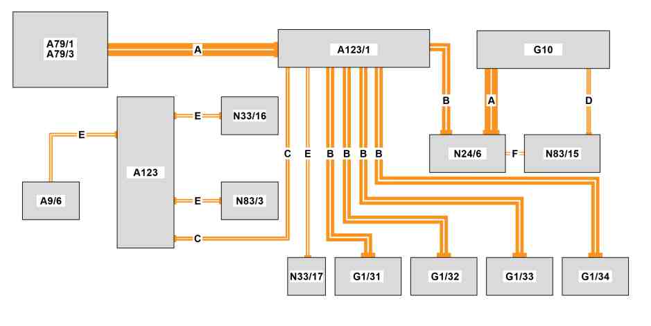
High-voltage on-board electrical system, schematic diagram |
A9/6 | Electric refrigerant compressor | N33/16 | High-voltage PTC heater control unit | |
A79/1 | Electric machine 1 | N33/17 | Battery heater control unit | |
A79/3 | Power electronics control unit | N83/3 | DC/DC converter control unit | |
A123 | High-voltage power distributor 1 | N83/15 | Alternating current charger for high-voltage battery | |
A123/1 | High-voltage power distributor 2 | A | High voltage line 2 x 50 mm2 | |
G1/31 | High-voltage battery 1 | B | High voltage line 2 x 35 mm2 | |
G1/32 | High-voltage battery 2 | C | High voltage line 2 x 16 mm2 | |
G1/33 | High-voltage battery 3 | D | High voltage line 4 x 6 mm2 | |
G1/34 | High-voltage battery 4 (with code E4T (High-voltage battery (47 kWh))) | E | High voltage line 2 x 6 mm2 | |
G10 | DC/AC charging vehicle socket | F | High voltage line 2 x 4 mm2 | |
N24/6 | Direct current charge connection unit |
All plugs are contact-protected.
Seating of all connector couplings is monitored by an interlock circuit.
All high-voltage lines are orange.
All high voltage components are marked with yellow warning stickers.

Warning notice regarding high-voltage on-board electrical system
High-voltage on-board electrical system with voltage class B (DC voltage 60 V < U 1500 V and AC voltage 30 V < U 1000 V):
Only specialist workshops with the appropriate specialists may carry out repairs and rectify faults on the high-voltage on-board electrical system.
S54.10-A050-71
High-voltage on-board electrical system, general
The function description comprises the following information in detail:
High-voltage on-board electrical system
Interlock circuit
High-voltage safety
High-voltage batteries heating
Energy management for high-voltage on-board electrical system
Energy distribution
Regenerative braking
Vehicle network support
Drive programs "C", "E", "E+"
Switching on and disconnecting the high-voltage on-board electrical system
Deactivation of high voltage on-board electrical system in event of accident and short circuit
Manual power disconnect of high-voltage on-board electrical system
High-voltage disconnect device (S7) (Service separating point in engine compartment)
Disable (de-energize)
Alternative high-voltage disconnect device in case of emergency (high-voltage rescue separation point)
High-voltage on-board electrical system
The high-voltage on-board electrical system enables the operation of electric machine 1 for the electric drive. In addition, the high-voltage on-board electrical system supplies consumers with high energy requirements such as the electric refrigerant compressor or the high-voltage PTC heater control unit with electrical energy. In certain driving situations, the electric machine 1 is used as an alternator to generate electrical energy (recuperation). The high-voltage on-board electrical system supplies the 12 V on-board electrical system with electrical energy from the high-voltage batteries via the DC/DC converter control unit.
The battery management system control unit (N82/2) takes over the complete monitoring of the high-voltage batteries with regard to the temperature, voltage and currents. It specifies the safety limits for these values and transmits values as well as safety limits to the powertrain control unit (N127).
The high-voltage on-board electrical system is supplied with energy from the high-voltage batteries in overrun mode via the power inverter integrated in the power electronics control unit (A79/3). The charging of the high-voltage batteries is realized in overrun mode via recuperation or when the vehicle is stationary via connection to an external power source via the AC charger for the high-voltage battery (N83/15) and/or the DC current charge-connection unit (N24/6). If the high-voltage batteries are almost completely discharged, the drive system switches off. The high-voltage batteries are thus protected from deep discharging.
Interlock circuit
The interlock circuit provides protection against accidentally touching the high voltage components. An interlock voltage signal is looped through all high-voltage on-board electrical system component parts that can be removed or opened. To do this there is an electrical bridge in each removable high-voltage connection which interrupts the interlock circuit during removal of the high-voltage connection.
The interlock circuit is also led switched in a series over the 12 V control units plug connection of the high-voltage components. When detaching a control units plug connection the interlock circuit is interrupted via the contacts interlock input and output. A discontinuity of the interlock circuit while driving does not lead to switching off of the high voltage on-board electrical system. If the ignition is switched off and interlock circuit has an open circuit, the vehicle can no longer be driven.
High-voltage safety
In the event of a crash or if the high-voltage disconnect device is opened, the following systems are deactivated:
High-voltage on-board electrical system
Charging system
Electrical drive

Location |
N33/17 | Battery heater control unit |
D54.10-A022-76
High-voltage batteries heating
Because the efficiency of the high-voltage batteries is dependent on temperature, it decreases significantly as the temperature drops. Depending on the state of charge and temperature of the high-voltage batteries, this will if necessary be heated up until the required amperage is enabled by the high-voltage batteries for vehicle operation or charge mode.
The high-voltage batteries are heated via the battery heater control unit (N33/17) that is integrated in the coolant circuit of the high-voltage batteries (low-temperature circuit 2) and ensures that the temperature of the high-voltage batteries does not fall below 15 °C during driving operation or charge mode.
The battery heater control unit is a high voltage PTC heater booster and is actuated by the powertrain control unit. The heating elements are heated by energizing them. The coolant flowing through the battery heater control unit absorbs the heat of the heating elements and is heated as a result. This support is maintained until a suitable temperature has been reached and then it is automatically ended.
Energy management for high-voltage on-board electrical system
The high-voltage on-board electrical system enables the operation of electric machine 1 for the electric drive. In addition, the high-voltage on-board electrical system supplies consumers with high energy requirements such as the electric refrigerant compressor or the high-voltage PTC heater control unit with electrical energy.
High-voltage on-board electrical system energy management manages the provision (supply) and consumption (balance) of electrical energy. The goal is a low energy consumption and an optimal charging process.
In certain driving situations, the electric machine is used in generator mode for generating electrical energy (recuperation). The high-voltage on-board electrical system supplies the 12 V on-board electrical system with electrical energy from the high-voltage batteries via the DC/DC converter control unit (N83/3).
The energy management function is integrated in the powertrain control unit (N127). Some of the basic tasks are listed in the following:
Activation and/or deactivation of high-voltage components in accordance with the high-voltage safety requirements
Determination of usable energy quantity in the high-voltage batteries
Energy distribution between the high-voltage components based on the available energy
Forecast of currently available electrical power of powertrain
Coordination of charging process (interaction of high-voltage batteries and charging components)
Calculation of the electric range and electric consumptions for the trip computer
Check of high-voltage safety requirements and as-required transfer to a safe state
The following components are extensively involved in high-voltage on-board electrical system energy management:
Electric machine 1 (A79/1)
Power electronics control unit (A79/3)
DC/AC charging vehicle socket (G10)
High-voltage battery 1 (G1/31)
High-voltage battery 2 (G1/32)
High-voltage battery 3 (G1/33)
Optional high-voltage battery 4 (G1/34) (with code E4T (High-voltage battery (47 kWh)))
DC current charge-connection unit (N24/6)
Battery management system control unit (N82/2)
DC/DC converter control unit (N83/3)
AC charger for high-voltage battery (N83/15)
Powertrain control unit (N127)
Energy distribution
The operation strategy in the vehicle is designed to control the flow of energy dynamically. Therefore the necessary energy is prepared for the arising driving condition in good time. To this much information flows in the intelligent controlling, which evaluates this information and allows the respective drive torques to be provided. Information includes the driver request, the requests on the vehicle and the environmental conditions.
Also the achievable service life of the energy storage system very much depends on the operating strategy. This in particular requires, in a heating case, an intelligent energy management, that uses all available energy sources, in order to increase the range of the vehicle. In this connection, the energy distribution to the high-voltage components is limited depending on the current driving situation (12 V on-board electrical system, heating and climate control functions).
Regenerative braking
The drive concept permits recuperation during vehicle deceleration. In this connection, the electric machine 1 is operated as an alternator and generates a braking torque at the wheels. The electrical energy generated in this connection flows back into the high-voltage batteries. Energy management controls the return flow of the energy.
For additional information, see the document "Recuperation function".
Vehicle network support
All implemented control units are supplied via the on-board electrical system battery (G1) of the 12 V on-board electrical system.
When the vehicle is stationary and the ignition is not switched on, all consumers are supplied by the on-board electrical system battery.
On-board electrical system support ensures that the on-board electrical system battery is charged at all times. The on-board electrical system is supported continuously via the DC/DC converter. The state of charge varies between 12 V and approx. 14.8 V depending on the charge level of the on-board electrical system battery and other environmental conditions.
The DC/DC converter control unit converts the high voltage from the high-voltage on-board electrical system to the voltage level of the 12 V on-board electrical system to supply the 12 V consumers and to charge the on-board electrical system battery. For this purpose, the DC/DC converter control unit receives a specified voltage input for the 12 V on-board electrical system from the SAM control unit (N10).
After the ignition gas been switched on, the available voltage of the on-board electrical system battery is checked and, as required, supercharged and supported via the DC/DC converter control unit by the high-voltage batteries. The consumers of the 12 V on-board electrical system continue to be supplied by the on-board electrical system battery. The high-voltage on-board electrical system is continuously switched in while driving.
The high-voltage batteries are charged externally by connecting the charging cable to the DC/AC charging vehicle socket (G10), the private mains supply (stationary house utilities connection) or a public mains supply (charging station). In addition, a "Mercedes-Benz Wallbox Home" is accessible. Mercedes-Benz battery-electric vehicles can be charged much quicker via this than via a conventional mains outlet.
Drive programs "C", "E", "E+"
The drive programs have different features in the mileage, in the response time of the accelerator pedal, and in the heating and climate control output. When considered together, these properties can result in different vehicle ranges.
For additional information, see the document "Electric vehicle function".
Switching on and disconnecting the high-voltage on-board electrical system
As a rule, the high-voltage on-board electrical system must be disabled with XENTRY Diagnosis.
The repair, maintenance and diagnostic activities in vehicles with high-voltage on-board electrical system may only be performed by qualified employees. Documented attendance of a high voltage training session is the minimum required qualification for this. Disconnecting (de-energization) of the high-voltage on-board electrical system before activities on the vehicle and for the subsequent commissioning following the activities may be performed only by an electrician for high-voltage on-board electrical systems in motor vehicles, series production vehicle field of activity.
Depending on the driving condition, e.g. charging, service, or accident, the high-voltage on-board electrical system can and must be switched on or disconnected.
Deactivation of high voltage on-board electrical system in event of accident and short circuit
Deactivation of the high voltage on-board electrical system in the event of an accident is initiated by triggering the pyrofuse. The separator is actuated by the Supplemental Restraint System control unit (SRS) (N2/5) if a crash is detected. It results in all-pole separation of the power sources, the deactivation of generator mode of electric machine 1 and the discharge of the capacitors to a value below the dangerous voltage range. A gradual deactivation of the high voltage on-board electrical system takes place in the event of a short circuit using software and electrical fuses.
In the event of an accident, a security system recognizes the severity of the crash and decides whether the high-voltage on-board electrical system must be switched off reversibly or irreversibly.
Reversible: A small amount of minor damage without triggering the airbag or impairing the high-voltage on-board electrical system. The high voltage buffer is discharged within a few seconds. The vehicle can be re-started via the ignition.
Irreversible: The power supply of the contactors is interrupted by a pyrotechnical element. The high voltage buffer is discharged within a few seconds. The vehicle cannot be started again by the operator.
Manual power disconnect of high-voltage on-board electrical system
When working on the high-voltage on-board electrical system, the system must be de-energized beforehand and the de-energized state of the high-voltage on-board electrical system must be ensured.
The three safety rules must be observed and adhered to when conducting such work:
Disable (de-energize)
Secure against reactivation.
Check and ensure absence of voltage (attach vehicle power disable event log to the vehicle so that it is clearly visible).
For the power disconnect of the high-voltage on-board electrical system with XENTRY Diagnosis, the safety information must be observed and the instructions must be followed.
Thus, before the activation of the high-voltage disconnect device (S7), for example, the actual values from the respective control unit are read out and evaluated and the lock of the high-voltage component lock is actuated in the control units.
In the event of an accident, voltage must also be removed from the vehicle by the rescue services.
Two high-voltage disconnect devices are available for the manual power disconnect:
High-voltage disconnect device (S7) (Service separating point in engine compartment)
Power disconnect of high-voltage on-board electrical system, e. g. for work in the workshop, but also in an accident.
Alternative high-voltage disconnect device in case of emergency (high-voltage rescue separation point)
Irreversible power disconnect of high-voltage on-board electrical system only for an emergency, e. g. in an accident.
High-voltage disconnect device (S7) (Service separating point in engine compartment)
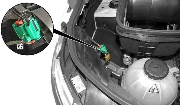
S7 | High-voltage disconnect device |
D08.00-A002-75
The high-voltage disconnect device (S7) serves to secure the power disconnect and is located on the right front module holder in the engine compartment.
The high-voltage disconnect device disconnects the power supply of the contactors so that these can no longer be activated.

S54.10-A001-77
Actuate high-voltage disconnect device (S7) |
1 | High-voltage disconnect device housing | 3 | Padlock | |
2 | Jumper plug | 4 | Fuse |
Disable (de-energize)
The bridging plug (2) is, as shown in the picture sequence (A, B, C), unlocked at retainer (4), pulled out of the high-voltage disconnect device housing (1) and secured with a padlock (3) against a restart procedure.
Alternative high-voltage disconnect device in case of emergency (high-voltage rescue separation point)
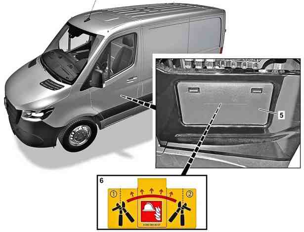
5 | Driver seat base cover |
6 | Information label (high-voltage rescue separation point) |
D08.00-A016-76
The alternative high-voltage disconnect device (high-voltage rescue separation point) must only be actuated if the high-voltage disconnect device (S7) in the engine compartment cannot be actuated, as this step is irreversible.
For the rescue services, there are two special adhesive labels with the QR Code® as a link to the rescue card. These are located on the driver's side B-pillar as well as on the front passenger side B-pillar and identify the location of the high-voltage on-board electrical system components as well as pyrotechnical devices and disconnect devices.
The alternative high-voltage disconnect device is located behind the driver seat base cover (5). It is identified with an information label (6) on the electric line. During this process, it is necessary to cut through the electric line at the marked separating point. The line is not located on the high-voltage on-board electrical system.
The standardized high-voltage rescue separation point serves the emergency forces for the irreversible shutoff of the high-voltage on-board electrical system in the case of rescue and recovery.