
D72.16-1399-09
Shown on model 907.7 |
1 | Sliding door | IB | Gap dimension | MA | Minimum distance | ||
2 | Guide rail in center | IC | Gap dimension | SV | Beading offset | ||
IA | Gap dimension | ID | Gap dimension |

Shown on model 907.6 with code T55 (electrical actuation for right sliding door) |
15 | Unlocking |
D72.16-1378-01

D72.16-1418-09
Shown on right sliding door (1) on model 907.6 with code D03 (Roof and rear-end doors, high version) |
1 | Sliding door | 6 | Bolts | 9 | Upper rotary tumbler | ||
3 | Screw | 7 | Centering cone | 10 | Counterpart | ||
4 | Lock striker | 8 | C-pillar | 11 | B-pillar | ||
5 | Striker pin |
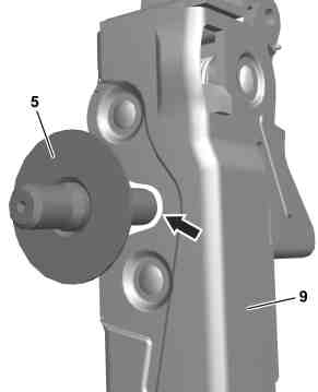
Shown on right upper rotary tumbler (9) on model 907.6 with code D03 (Roof and rear-end doors, high version) |
5 | Striker pin |
9 | Upper rotary tumbler |
D72.16-1442-02
Warning | Risk of injury caused by fingers being jammed or pinched when removing, installing or aligning hoods, doors, trunk lid/rear-end door or sliding roof. | No parts of the body or limbs should be within the operating area when the components are moving. | |
| Check | ||
1 | Check gap dimensions (IA, IB, IC, ID) on sliding door (1). | ||
| |||
Gap dimensions of sliding door | |||
Feeler gauge | |||
2 | Check beading offset (SV) on the sliding door (1). | | |
Gap dimensions of sliding door | |||
Maximum bead offset | |||
3 | Check minimum distance (MA) between sliding door (1) and center guide rail (2). | Minimum distance from sliding door to center guide rail | |
Feeler gauge | |||
4 | Check transition between sliding door (1) and B-pillar (11). | The contour of the B-pillar (11) must be flush with the contour of the sliding door (1) or may protrude by max. 1 mm. | |
5 | Check transition between sliding door (1) and C-pillar (8). | The contour of the sliding door (1) must be flush with the contour of the C-pillar (8) or may protrude by max. 1 mm. | |
Preparatory tasks | |||
6 | Open sliding door (1) and set release (15) on sliding door (1) to "MAN" position with a suitable screwdriver. | Model 907.6/7 | |
This deactivates the electric drive of the sliding door (1). | |||
7 | Loosen screws (3) until the lock striker (4) can be moved. | ||
8 | Loosen striker pin (5) until it can be moved. | Model 907.6/7/8, 910.6 | |
9 | Loosen screws (6) until the centering cone (7) can be moved. | ||
Adjustment of the sliding door (1) in terms of height and longitudinal direction | |||
10 | Adjust gap dimensions (IA, IB, IC, ID), beading offset (SV), and minimum distance (MA). | ||
Gap dimensions of sliding door | |||
Maximum bead offset | |||
Minimum distance from sliding door to center guide rail | |||
Model 907.6/7/8 | |||
Bolt, carriage in center to sliding door | |||
Bolt, holder for carriage at bottom to sliding door | |||
Bolt, door check at top to sliding door | |||
Bolt, door check at bottom to sliding door | |||
Feeler gauge | |||
Adjustment of the transitions between the sliding door (1) and body | |||
11 | Adjust transition between sliding door (1) and B-pillar (11) and transition between sliding door (1) and C-pillar (8). | ||
Bolt, lock striker to C-pillar | |||
Bolt, carriage to holder | |||
Fix end position of the sliding door (1) | |||
12 | Adjust position of the striker pin (5) relative to the top rotary tumbler (9) by moving it and then tighten. | Model 907.6/7/8, 910.6 | |
| |||
13 | Lightly tighten screws (6) by hand. | It must still be possible to move the centering cone (7). | |
14 | Open and close sliding door (1) twice. | During this process, the centering cone (7) in the counterpart (10) is centered to the B-pillar (11). | |
15 | Tighten screws (6) on the centering cone (7). | Bolt, centering pin to sliding door | |
Concluding tasks | |||
16 | Set release (15) on sliding door (1) to "AUTO" position with a suitable screwdriver. | Model 907.6/7 | |
This re-activates the electric drive of the sliding door (1). | |||
17 | Fully open and close the sliding door (1) twice using the corresponding push button switch. | Model 907.6/7 | |
For the normalization of the electrical drive of the sliding door (1). |
Test and adjustment values for gap dimensions |
Number | Designation | Model 907.6/7/8, 910 | |||
BE60.00-N-1009-01TS | Gap dimensions of sliding door | Sliding door to B-pillar | Dimension "IA" | mm | 6,0 (1) |
Sliding door to longitudinal member | Dimension "IB" | mm | 5,5 (1) | ||
Sliding door to C-pillar | Dimension "IC" | mm | 6,0 (1) | ||
Sliding door to roof frame | Dimension "ID" | mm | 5,5 (1) | ||
Glass pane in sliding door to glass pane in sidewall | Dimension "IE" | mm | 10 (1) | ||
For picture, see | |||||
Check values for sliding doors |
Number | Designation | Model 907.6/7/8 | Model 907.6/7/8 | |
BE72.16-N-1001-01TS | Maximum bead offset | mm | 1,0 | 1,0 |
Check values for sliding doors |
Number | Designation | Model 907.6/7/8 | Model 907.6/7/8 | |
BE72.16-N-1003-01TS | Minimum distance from sliding door to center guide rail | mm | 3...4 | 3...4 |

129 589 03 21 00
Feeler gauge
Powiązane dokumenty
- ar6000d070001ts
- ar7216d102301ts
- ar7216d102305ts
- as0000z001101a Niebezpieczeństwo zranienia przez zakleszczenie lub zmiażdżenie palców podczas demontażu, montażu i prac regulacyjnych przy pokrywach, drzwiach i oknie dachowym.