Additional information can be found in the superordinate service document.
The safety information in the superordinate service document must be observed.
The following operation steps are shown for model 907.633.

D64.20-A001-09
a | Dimension (approx. 65 mm) |
1 | Model 907.6/7 |
2 | Expose spot welds at rear-end center section inner part (1) (areas A, B, C, D, E and F). |
Commercially available devices/tools |
3 | Cut off spot welds at rear-end center section inner part (1) (areas A, B, C, D, E and F). |
Commercially available devices/tools |
4 | Expose weld seams at rear-end center section inner part (1) (areas G, H, I, J, L1, L2, M1 and M2). |
Commercially available devices/tools |
5 | Cut weld seams at rear-end center section inner part (1) (areas G, H, I, J, L1, L2, M1 and M2). |
Commercially available devices/tools |
6 | Mark separating point on rear-end center section inner part (1) (area K). |
Observe dimension (A). |
7 | Cut rear-end center section inner part (1) at separating point (area K). |
Do not cut too deeply. |
Commercially available devices/tools |

8 | Expose spot welds at rear-end center section inner part (1) (areas N and O). |
Commercially available devices/tools |
9 | Cut off spot welds at rear-end center section inner part (1) (areas N and O). |
Commercially available devices/tools |
10 | Mark separating point, as shown, on rear-end center section inner part (1) (area P). |
11 | Cut rear-end center section inner part (1) at separating point (area P). |
Do not cut too deeply. |
Commercially available devices/tools |
12 | Remove damaged rear-end center section inner part (1). |
D64.20-A002-06
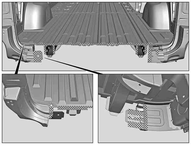
13 | Grind mating surfaces down to bare metal in cross-hatched areas and around hole. |
Sand down spot weld flanges to bare metal on both sides. |
Commercially available devices/tools |
14 | Remove shavings and milling chips. |
Commercially available devices/tools |
15 | Zinc dust paint to insides of spot weld flanges. |
D64.20-A003-06