ar6320d110403ts

Prepare A-pillar inner section for installation

Typ ar · temat 63.20 · wersja 0100 · 2018-03-27

Dotyczy: Model 907, 910

Niedostępne w języku „pl”; wyświetlono w języku Angielski.

Umiejscowienie

Grupa funkcyjna 3 Nadwozie › 63 Ściana boczna › 63.20 Słupki — Seria 907 · Seria 910

EinPAS 35 Karoseria/ rama/ elementy domontowane › 35.34 Ściana boczna › 35.34.45 Słupek — Seria 907 · Seria 910

AR63.20-D-1104-03TS

Prepare A-pillar inner section for installation

Caution

Risk of injury caused by scraping or cutting body parts on sharp vehicle parts

Always wear protective gloves when working on or near sharp and non-deburred vehicle parts.
Deburr repair panels.

AS00.00-Z-0017-01A

Model

907, 910

Repair materials

Number

Designation

Order number

BR00.45-Z-1056-07A

1K-zinc dust paint

A 000 986 28 00

The following operation steps are shown on the left component parts and must be similarly performed on the right side of the vehicle in the case of damage.

Prepare A-pillar inner section for installation

1

Scribe separation line on upper A-pillar inner section (1.1) (area A).


Apply dimension for separation line from vehicle.


2

Separate upper A-pillar inner section (1.1) at the separation point (area A).


3

Dispose of remaining piece.


4

Grind down mating surfaces to bare metal in cross-hatched areas.


Sand down spot weld flanges to bare metal on both sides.


5

Remove shavings.


6

Zinc dust paint to insides of spot weld flanges.


D63.20-1500-05

Prepare A-pillar inner section for installation

D63.20-1501-08

7.1

Model 907
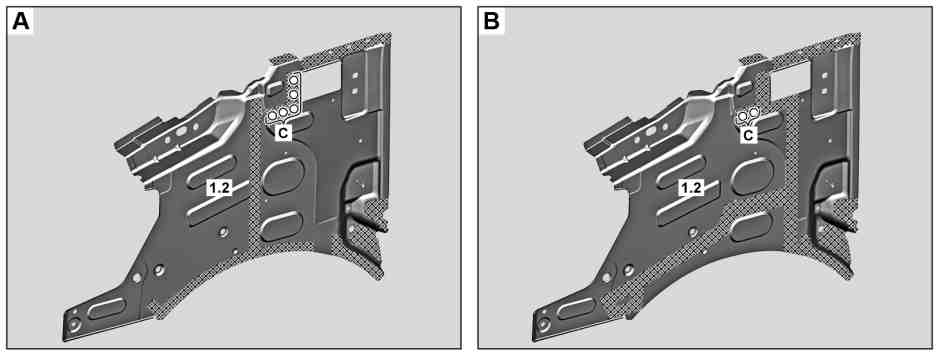
Drill holes in center A-pillar inner section (1.2) with Ø 8 mm drill bit (area C) (figure A).

7.2

Model 910
Drill holes in center A-pillar inner section (1.2) with Ø 8 mm drill bit (area C) (figure B).

8.1

Model 907
Grind mating surfaces down to bare metal in cross-hatched areas and around holes (area C) (figure A).

Sand down spot weld flanges to bare metal on both sides.

8.2

Model 910
Grind mating surfaces down to bare metal in cross-hatched areas and around holes (area C) (figure B).

Sand down spot weld flanges to bare metal on both sides.

9

Remove shavings and drill chips.

10

Zinc dust paint to insides of spot weld flanges.

Prepare A-pillar inner section for installation

11

Grind down mating surfaces to bare metal in cross-hatched areas.


Sand down spot weld flanges to bare metal on both sides.


12

Remove shavings and drill chips.


13

Zinc dust paint to insides of spot weld flanges.


D63.20-1502-05

Powiązane dokumenty