
Shown on model 907.633 with code D03 (Roof and rear-end doors, high version), left side of vehicle |
1 | Wheel well |
D62.20-0155-05

D60.00-A003-09
Shown on model 907 with engine 651 with code HH4 (THERMOTRONIC automatic climate control) |
4 | Refrigerant lines | 7 | Ventilation box | |
6 | Coolant line | 8 | AdBlue® tank |
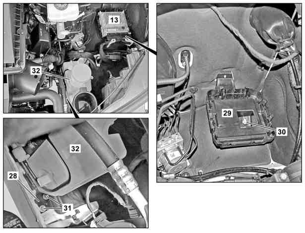
Shown on model 907 with engine 651 |
13 | Diesel injection system control unit |
28 | Bracket |
29 | Bracket |
30 | Nut |
31 | Nuts |
32 | Washer fluid reservoir |
D60.00-A010-06
| Remove/install | ||
1 | Remove front-end assembly. | ||
2 | Remove each front wheel. | ||
3 | Remove washer fluid reservoir (32) of windshield washer system. | If left side of vehicle is damaged. | |
4 | Remove bracket (28) for the washer fluid reservoir (32) of the windshield washer system. | If left side of vehicle is damaged. | |
For this purpose, remove nuts (31). | |||
5 | Remove battery carrier of auxiliary battery in engine compartment. | If left side of vehicle is damaged. | |
Model 907 | |||
6 | Remove ESP® hydraulic unit. | If left side of vehicle is damaged. | |
7 | Remove AdBlue® tank (8). | If right side of vehicle is damaged. | |
Model 907 with engine 642 | |||
8 | Remove refrigerant lines (4) in the repair area of the wheel well (1) and position outside of the working area. | Model 907 with code HH4 (THERMOTRONIC automatic climate control) or with code HH9 (semi-automatically controlled air conditioning system, TEMPMATIC) | |
9 | Remove coolant line (6) in the repair area of the wheel well (1) and position outside of the working area. | If right side of vehicle is damaged. | |
10 | Remove ventilation box (7). | In the case of damage to front passenger side. | |
11 | Remove respective front section of front fender liner. | ||
12 | Remove diesel injection system control unit (13). | If left side of vehicle is damaged. | |
Model 907 with engine 642, 651 | |||
13 | Remove bracket (29) of the diesel injection system control unit (13). | Model 907 with engine 642, 651 | |
To do this, remove nut (30). | |||
14 | Remove respective electrical wiring harness in the repair area of the wheel well (1) and position outside of the working area. | ||
15 | Remove respective dampings in the repair area of the wheel well (1) and position outside of the working area. | ||
16 | Install in the reverse order. |