
P33.10-2205-09
Shown on model 219 with steel suspension
1 Front axle carrier
1a Screw
1b Screw
5 Steering knuckle
9 Steering coupling
18 Torque strut
18a Screw
78 Stabilizer bar
78k Link rod
10 Rack-and-pinion steering
10a Tie rod joint
17 Spring control arm
17a Screw
17d Joint piece

P33.10-2109-07
Shown on model 219 with steel suspension
1 Front axle carrier
1b Screw
9 Steering coupling
10 Rack-and-pinion steering
30f Oil line
30i Oil line
Y10 SPS [PML] solenoid valve
11 Front engine mount
12 Retaining plate
13 Screw
Modification notes
| Remove/install | ||
Danger! | Risk of injury to skin or eyes caused by hydraulic fluid spraying out under high pressure. Risk of poisoning caused by swallowing hydraulic fluid | Depressurize the hydraulic system completely before starting any work on the system. Wear protective clothing and safety glasses. | |
| Notes on self-locking nuts and bolts | ||
| When working on the front-end assembly, be careful not to scratch, mark or notch the surfaces of aluminum parts. Otherwise the service life of the parts will be affected | ||
Installation | Only tighten nuts and bolts of chassis components when vehicle is in a ready-to-drive condition. | ||
1 | Deactivate easy entry/exit function | Vehicles with memory package (driver seat, steering column, mirrors) code 275 | |
Otherwise the driver seat and steering wheel move to a different position, e.g. when the driver door is opened/closed. The upper frame may be damaged when the holding device is installed. | |||
The system is switched off via the buttons on the steering wheel in the "Comfort" menu of the multifunction display. | |||
2 | Turn front wheels to straight-ahead position and secure steering wheel with holding device | On a disengaged steering coupling (9) the steering wheel should not be turned because the spiral contact coil will be destroyed. | |
To do this, turn sun visor to side and insert holding device. | |||
| |||
3 | Remove air filter housing with air ducts | Model 219.377 | |
Model 219.354 /356 /357 /372 | |||
Model 219.375 | |||
Model 219.376 | |||
Model 219.322 | |||
4 | Extract oil from power steering expansion reservoir | | |
5 | Attach engine support frame | ||
| |||
6 | Raise engine until front engine mounts (11) are relieved of load | Make sure that the engine is not raised too far, otherwise the engine mounts (11) can be damaged. | |
7 | Remove the front wheels | ||
| Remove/install wheels | ||
8.1 | Remove bottom engine compartment paneling | Vehicles with gasoline engine | |
Installation: Only install the engine compartment paneling after the leak check on the rack-and-pinion steering (10). | |||
8.2 | Remove bottom section of soundproofing | Vehicles with diesel engine | |
Installation: Do not install bottom section of soundproofing until after rack-and-pinion steering (10) has been checked for leaks. | |||
9 | Press tie rod joints (10a) out of steering knuckles (5). | ||
| |||
| |||
| |||
10 | Detach torque struts (18) from front axle carrier (1) | Do not twist bolt (18a). Counterhold bolt (18a) when slackening the nut. Otherwise the fixing lugs for the caster adjustment in the rubber mount will be sheared off when the repair kit is fitted. | |
| |||
11 | Remove link rod (78k) from stabilizer bar (78) on pivot bushing (17d) in the spring control arm (17) | Necessary on left and right side of vehicle. | |
| |||
12 | Remove left and right spring control arms (17) from front-axle carrier (1). | Bolt (17a) must not be twisted. When loosening the nut, the bolt (17a) must be counterheld, as the fixing lugs for camber adjustment in the rubber mount are otherwise sheared off. | |
| |||
| |||
13 | Pull steering coupling (9) off rack-and-pinion steering (10). | ||
14 | Detach front engine mount (11) from front axle carrier (1) | Vehicles with gasoline engine | |
Vehicles with diesel engines | |||
15 | Separate electrical connector from SPS [PML] solenoid valve (Y10) | ||
16 | Remove cable tie (arrow) and place electric feed line of SPS [PML] solenoid valve (Y10) to the side | ||
17 | Remove retaining plate (12) and bolt (13) from rack-and-pinion steering (10), pull oil lines (30f, 30i) out of rack-and-pinion steering (10) and set aside | See Remove/install rack-and-pinion steering (10). | |
Before opening the hydraulic circuit of the rack-and-pinion steering (10) the area around the separation point should be cleaned thoroughly. Even minute particles of dirt, introduced into the hydraulic components, can result in malfunctions of the rack-and-pinion steering (10). | |||
Collect escaping hydraulic fluid in a container and seal connections with stop plugs. | |||
Installation: Replace O-rings. | |||
| |||
18 | Support and secure the front subframe (1) with the transmission jack and transmission plate | ||
19 | Undo bolts (1a) and bolts (1b) | | |
| |||
20 | Pull the left and right front axle halves outwards and lower the front axle carrier (1) | ||
21 | Check front axle carrier (1) | Check for damage and replace if necessary: | |
Remove/install stabilizer bar (78) from front axle carrier (1). | |||
Installation: The retaining brackets on the stabilizer bar (78) must be replaced. | |||
Remove/install rack-and-pinion steering (10) of front axle carrier (1). | |||
Detach/attach left and right heat shield at front axle carrier (1). | |||
22 | Install in the reverse order | ||
23 | Fill power steering pump and bleed | Model 219.354 /356 /357 /372 /322 | |
Model 219.375 /376/ 377 | |||
24 | Check steering for function and leaks | ||
25 | Perform a wheel alignment check |
Engine suspension, engine mounts, engine supports
Number | Designation | Engine | ||
BA22.10-P-1001-01D | Bolt, front engine mount to front axle carrier | Nm | 35 | |
Engine suspension, engine mounts, engine supports
Number | Designation | Engine | Engine | ||
BA22.10-P-1001-01S | Bolt, front engine mount to front axle carrier | Nm | 35 | 35 | |
Engine suspension, engine mounts, engine supports
Number | Designation | Engine | ||
BA22.10-P-1001-01S | Bolt, front engine mount to front axle carrier | Nm | 35 | |
Front axle stabilizer bar
Front axle carrier
Number | Designation | Model | |
BA33.10-P-1001-01J | Bolt, retaining bracket to front end | Nm | 50 |
BA33.10-P-1002-01J | Bolt, front axle carrier to longitudinal member | Nm | 100 |
Tie rod
Number | Designation | Model | ||
BA46.40-P-1001-01E | Self-locking nut, tie rod to steering knuckle | Stage 1 | Nm | 50 |
Stage 2 | ° | 90 | ||
Wheel location, hub
Number | Designation | Model | ||
BA33.20-P-1005-01K | Self-locking nut, spring control arm to front axle carrier | Stage 1 | Nm | 80 |
Stage 2 | ° | 120 | ||
BA33.20-P-1006-01K | Self-locking nut, torque strut to front axle carrier | Stage 1 | Nm | 80 |
Stage 2 | ° | 120 | ||
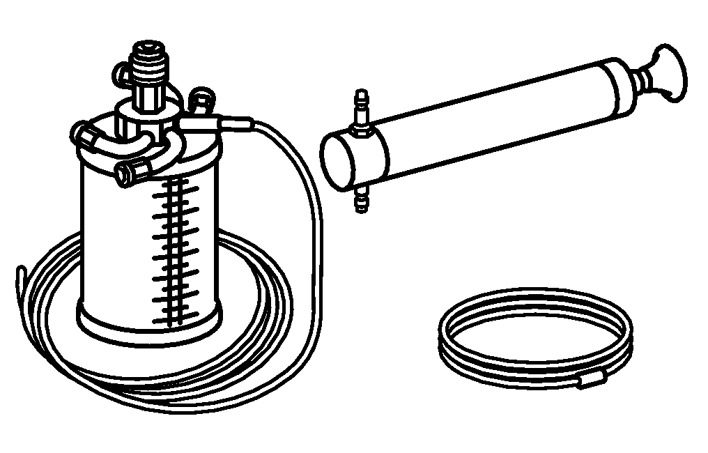


210 589 00 71 00
Hand pump
Holding device
129 589 01 21 00
Box wrench bit
211 589 00 03 00
129 589 00 91 00
Set of stop plugs


140 589 00 63 00
Puller
Thrust piece
Engine lifting fixture
240 589 00 61 00
140 589 00 33 00
Powiązane dokumenty
- ah0000n000101a Wskazówki dotyczące samozabezpieczających śrub i nakrętek
- ap4010p4050tx Demontaż i montaż kół, w razie potrzeby przełożenie
- ar0910p1150tmg Demontaż i montaż obudowy filtra powietrza
- ar0910p1150tq Demontaż i montaż obudowy filtra powietrza
- ar0910p1150ts Demontaż i montaż obudowy filtra powietrza
- ar0910p1150ty Demontaż i montaż obudowy filtra powietrza
- ar0910p1150tz Demontaż i montaż obudowy filtra powietrza
- ar3220p0300tx
- ar3310p010001tx
- ar3310p010003tx
- ar4020p0200tx
- ar4610p8000tx
- ar4620p0600tx
- ar4630p0010tx
- ar4630p0010ty
- ar4640p020002tx
- ar6120p1105tx
- ar9430p5300tx
- as0000z001301a Niebezpieczeństwo obrażeń oczu i skóry przez płyn hydrauliczny pod ciśnieniem. Niebezpieczeństwo zatrucia w wyniku spożycia płynu hydraulicznego