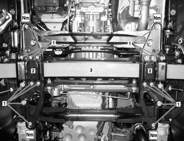
1 | Bolts |
2 | Clamping plate |
3 | Front axle spring |
D32.20-1112-06


D32.20-1123-01
D32.20-1122-01
D33.20-1124-01
7 | Torsion bar linkage |
8 | Stop plate |
Shown with code ZG1 (All-wheel drive, engageable) |
9 | Reinforcement plate (with code ZG1 (All-wheel drive, engageable) or with code ZG3 (Engageable all-wheel drive with transmission ratio)) |
Shown with code LG7 (LED High Performance headlamp) |
10 | Transverse control arm |
11 | Articulated rod (with code LG7 (LED High Performance headlamp)) |
Danger | Risk of death caused by vehicle slipping or toppling off of the lifting platform. | Align vehicle between vehicle lift columns and position the four support plates at the vehicle lift support points specified by the vehicle manufacturer. | |
Warning | Risk of injury caused by pinching or crushing when working on springs or spring bodies that are under tension | Use only approved tensioning devices; additionally screen off hazardous area if necessary. Check special tools for damage and proper operation (visual inspection). Wear protective gloves. | |
Topical note | Notes on threaded connections fastened using a tightening angle-based tightening process | ||
Topical note | Notes on self-locking nuts and bolts | ||
Notes on repair work on suspension components | |||
| Remove/install | ||
1 | Remove front wheels. | ||
2 | Secure vehicle on vehicle lift with tensioning straps. | ||
Commercially available devices/tools | |||
3 | Remove lower engine compartment paneling. | If installed. | |
4 | Remove clamping plate (2) at left and right. | | |
To do this, remove screw/bolts (1) . | |||
Screw, lower spring clamp plate to front axle carrier | |||
5 | Remove left and right torsion bar linkage (7) from stabilizer bar. | ||
6 | Remove bump stop of left and right stop plate (8). | Model 907 | |
To do so, remove screws of bump stop. | |||
Bolt, stop plate to transverse control arm/bump stop | |||
7 | Remove screws of left and right stop plate (8). | Bolt, stop plate to transverse control arm/bump stop | |
8 | Remove left and right stop plate (8) from transverse control arms (10). | ||
9 | Remove ball head of articulated rod (11) of front axle headlamp range control level sensor from transverse control arm (10). | Model 907 | |
10 | Remove left drive shaft on output flange of front axle differential. |
| |
Bolt, input shaft to front axle gear | |||
Loctite 262 | |||
11 | Loosen left transverse control arm (10) on front axle and pry out. |
| |
Model 907 | |||
12 | Remove reinforcement plate (9). | Model 907 | |
Bolt, reinforcement plate to front axle carrier | |||
13 | Remove front axle spring (3). | Aid of helper required. | |
| Check | ||
14 | Check spring bearings for wear and damage. | If corresponding findings are present, | |
| |||
Install a new spring bearing. | |||
15 | Install in the reverse order. |
Powiązane dokumenty
- ah0000n000101a Wskazówki dotyczące samozabezpieczających śrub i nakrętek
- ah0000p002001a Wskazówki dotyczące połączeń śrubowych tworzonych według kąta dokręcenia
- ah0000p010001a Wskazówki dotyczące napraw komponentów zawieszenia
- ar0060d010001ts
- ar3235d3330ts
- ar3320d1452tsr
- ar3320d1452tsx
- ar3330d010001tsx
- ar4010d1100ts
- ar6120d1105ts
- as0000z000101a Niebezpieczeństwo obrażeń na skutek zakleszczenia lub zmiażdżenia podczas czynności przy wstępnie naprężonych resorach lub elementach sprężynujących.
- as0000z001001a Zagrożenie życia na skutek ześlizgnięcia lub spadnięcia pojazdu z podnośnika.