
D25.10-A000-09
1 | Guide bearing | 3 | Clutch plate | 5 | Screws (6 ea.) | ||
2 | Flywheel | 4 | Clutch pressure plate | 6 | Centering drift | ||
2a | Friction surface | 4a | Friction surface | 7 | End stop |
Caution | Risk of injury caused by scraping or cutting body parts on sharp vehicle parts | Always wear protective gloves when working on or near sharp and non-deburred vehicle parts. | |
Topical note | Notes on working on clutch operating system | ||
Topical note | Notes on self-locking nuts and bolts | ||
| Remove | ||
1 | Remove transmission. |
| |
Model 910 with engine 651 with transmission 700.76 | |||
Model 907 with engine 642, 651 with transmission 711.6 | |||
2 | Remove bolts (5). | | |
When unscrewing the screws (5), ensure that the end stop (7) loosens from the clutch pressure plate (4) as shown. | |||
If end stop (7) does not loosen | |||
| |||
when unscrewing screws (5), push bolt of end stop (7) against flywheel (2) as shown using suitable tool. | |||
If end stop (7) still does not loosen: | |||
| |||
Replace clutch pressure plate (4) and clutch plate (3) as a set. | |||
3 | Remove clutch pressure plate (4) and clutch plate (3) from flywheel (2). | ||
| Check | ||
4 | Check end stop (7) for unobstructed movement in clutch pressure plate (4). | If end stop (7) does not move freely: | |
| |||
Replace clutch pressure plate (4) and clutch plate (3) as a set. | |||
5 | Check clutch pressure plate (4) and clutch plate (3) for damage and wear. | ||
Assembly cleaner | |||
If parts are damaged or worn, | |||
| |||
Replace clutch pressure plate (4) and clutch plate (3) as a set. | |||
6.1 | Check flywheel (2) for wear. | Model 907 with engine 642 with transmission 711.6 | |
If corresponding findings are present, | |||
| |||
replace flywheel (2). | |||
6.2 | Check flywheel (2) for wear. | Model 907 with engine 651 with transmission 700.790 | |
Topical note | Notes on evaluating two-mass flywheels | ||
Model 907.1/2/6 with engine 654.9 with transmission 711.6 | |||
Model 910 with engine 651 with transmission 700.760 | |||
Model 907 with engine 651 with transmission 700.790 | |||
If corresponding findings are present, | |||
| |||
replace flywheel (2). | |||
7 | Check central clutch release bearing for leak tightness and damage. | ||
Notes on working on central clutch release bearing of transmission | |||
If corresponding findings are present, | |||
| |||
replace central clutch release bearing. | |||
| |||
| |||
| |||
8 | Check radial shaft sealing ring at drive side for leak tightness and damage. | If corresponding findings are present, | |
| |||
Replace radial shaft sealing ring at drive side on transmission. | |||
| |||
| |||
9 | Check guide bearing (1) for wear. | If corresponding findings are present, | |
| |||
replace flywheel (2). | |||
Remove/install a flywheel | |||
| |||
| |||
| |||
| Install | ||
10 | Remove friction surface (2a) on flywheel (2) using coarse abrasive paper. | If flywheel (2) is not replaced. | |
11 | Remove friction surface (4a) on clutch pressure plate (4) using coarse abrasive paper. | If clutch pressure plate (4) is not replaced. | |
12 | Position, center and install clutch pressure plate (4) and clutch plate (3) on flywheel (2) using centering pin (6). | | |
Alignment punch | |||
13 | Fix clutch pressure plate (4) in place on flywheel (2) and screw in 3 screws (5). | When doing so, only screw in screws (5) by approx. one turn. | |
Alignment punch | |||
14 | Position remaining screws (5) and tighten. | | |
Model 907 with engine 651 | |||
Aid of helper required. | |||
Bolt, clutch pressure plate to flywheel | |||
Typ 907.6 mit Motor 654.9 mit Code HK4 (Heckklimaanlage, verstärkt) | |||
Typ 907.1/2/6 mit Motor 654.9 | |||
Typ 907 mit Motor 642 | |||
Typ 907 mit Motor 651 | |||
Typ 907 mit Motor 651 | |||
Typ 910 mit Motor 651 | |||
15 | Remove centering pin (6). | Alignment punch | |
16 | Install transmission. |
| |
Model 910 with engine 651 with transmission 700.76 | |||
Model 907 with engine 642, 651 with transmission 711.6 |


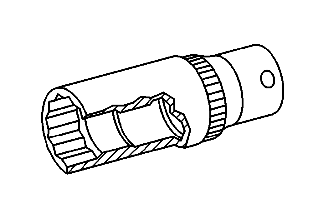
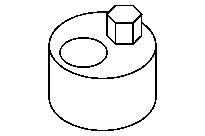
651 589 10 40 00
Counterholder
654 589 00 40 00
Counterholder
001 589 65 09 00
Socket wrench bit
651 589 00 40 00
Counterholder
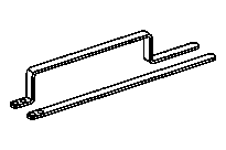


651 589 08 40 00
Counterholder
201 589 08 15 00
Alignment punch
654 589 03 40 00
Counterholder
Powiązane dokumenty
- ah0000n000101a Wskazówki dotyczące samozabezpieczających śrub i nakrętek
- ah0330n100002a Wskazówki dotyczące oceny dwumasowych kół zamachowych
- ah2520n000301ts Wskazówki dot. prac przy układzie uruchamiania sprzęgła
- ah2640n100101s Wskazówki dotyczące prac przy centralnym wysprzęgniku skrzyni biegów
- ar0330d8002tsf
- ar0330d8002tsm
- ar0330d8002tsr
- ar0330d8002tsv
- ar2510d005005ts
- ar2520a0180tsl
- ar2610a0020tsl
- ar2610d0020tsf
- ar2610d0020tsr
- ar2640d0345tsf
- ar2640d0345tsf
- ar2640d0345tsr
- ar2640d3258tsf
- ar2640d3258tsr
- as0000z001701a Niebezpieczeństwo obrażeńo elementy pojazdu o ostrych krawędziach.