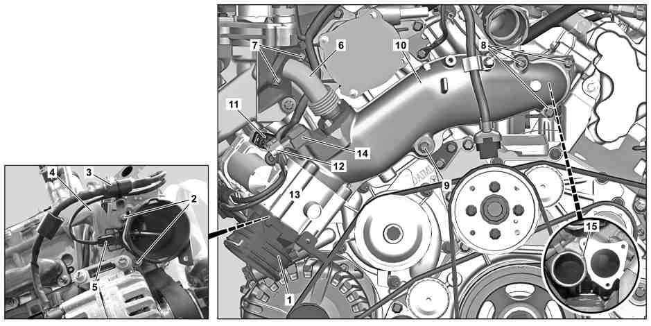
D09.20-1050-09
1 | Fitting | 6 | Exhaust gas recirculation line | 11 | Electrical connector | ||
2 | Bolts | 7 | Bolts | 12 | Electrical connector | ||
3 | Electrical wiring harness | 8 | Bolts | 13 | Throttle valve actuator | ||
4 | Bracket | 9 | Screw | 14 | Boost pressure sensor | ||
5 | Electrical connector | 10 | Mixing chamber | 15 | Sealing ring |
Danger | Risk of death caused by vehicle slipping or toppling off of the lifting platform. | Align vehicle between vehicle lift columns and position the four support plates at the vehicle lift support points specified by the vehicle manufacturer. | |
Warning | Risk of burn injuries, suffocation and poisoning when working on the exhaust system and the components connected to it. Risk of suffocation and risk of poisoning caused by inhalation of gaseous and solid components of the exhaust. Risk of poisoning caused by skin contact with solid components of the exhaust. | Wear protective clothing and safety glasses. Use the extraction system. Move people out of the hazard area. | |
Topical note | Information on preventing damage to electronic components due to electrostatic discharge | ||
Topical note | Notes on avoiding damage through contamination and foreign objects | ||
| Remove/install | ||
1 | Detach ground line of on-board electrical system battery. | ||
2 | Raise vehicle. | ||
Topical note | Special instructions for lifting and supporting vehicle | ||
3 | Remove bottom engine compartment paneling. | If installed. | |
4 | Remove charge air hose downstream of charge air cooler from fitting (1). | ||
Assembly tool | |||
5 | Remove screws (2). | Bolt, throttle valve actuator holder to cylinder head | |
Bolt, fitting to throttle valve actuator | |||
6 | Remove electrical wiring harness (3) from bracket (4). | Installation: Check retaining clip. | |
Depending on the findings, | |||
| |||
Replacing retaining clip. | |||
7 | Disconnect electrical connector (5). | ||
8 | Lower vehicle. | ||
9 | Remove fan with fan shroud. | ||
10 | Remove exhaust gas recirculation line (6) from exhaust gas recirculation valve housing. | To do this, remove bolts (7). | |
Installation: Replace seal. | |||
Bolt, exhaust gas recirculation line to housing of exhaust gas recirculation valve | |||
11 | Remove screws (8). | Screw/bolt, mixing chamber to charge air distributor | |
12 | Remove mixer housing (10). | Unscrew screw (9) to do this. | |
Installation: Replace seal and sealing ring (15) at charge-air distributor. | |||
Bolt, mixing chamber to support brace | |||
13 | Separate electrical connector (11). | ||
14 | Remove mixer housing (10). | For this purpose, disconnect electrical connector (12). | |
15 | Transfer fitting (1) and throttle valve actuator (13). | If mixer housing (10) is replaced. | |
16 | Transfer boost pressure sensor (14). | If mixer housing (10) is replaced. | |
17 | Transfer exhaust gas recirculation line (6). | If mixer housing (10) is replaced. | |
| Clean | ||
18 | Clean sealing surfaces at charge-air distributor and fitting (1). | Assembly cleaner | |
19 | Clean sealing surfaces at mixer housing (10). | If mixer housing (10) is not replaced. | |
Assembly cleaner | |||
20 | Install in the reverse order. | ||
| Check | ||
Warning | Risk of accident from vehicle starting off by itself when engine running. Risk of injury (bruises and burns) resulting from working on the engine while it is being started or when it is running. | Secure vehicle to prevent it from starting off by itself. Wear closed and snug-fitting work clothes. Do not touch hot or rotating parts. | |
21 | Check for leaktightness when engine is running. | Visual inspection only. |

000 589 93 63 00
Assembly tool
Powiązane dokumenty
- ah0000p500001a Wskazówki dotyczące zapobiegania uszkodzeniom na skutek zabrudzeń i ciał obcych
- ah0060n010001ts Wskazówki dotyczące podnoszenia pojazdu, ustawiania na podporach
- ah5400p000101a Wskazówki dotyczące zapobiegania uszkodzeniom elementów elektronicznych na skutek rozładowania potencjału elektrostatycznego
- ar0060d100004ts
- ar0941d0004tsv
- ar0941d131101we Otwieranie i zamykanie złącza
- ar0941d1330tsv
- ar1420d1063tsv
- ar2040d6800tsv
- ar5410d0029ts
- ar5410d0029ts
- ar5410d0029ts
- ar6120d1105ts
- as0000z000501a Niebezpieczeństwo wypadku na skutek samoczynnego ruszenia przy pracującym silniku. Niebezpieczeństwo obrażeń na skutek zmiażdżenia lub poparzenia przy wykonywaniu czynności podczas rozruchu lub przy pracującym silniku.
- as0000z001001a Zagrożenie życia na skutek ześlizgnięcia lub spadnięcia pojazdu z podnośnika.
- as4900z000101a Niebezpieczeństwo poparzenia, uduszenia i zatrucia podczas prac przy układzie wydechowym i połączonych z nim elementach. Niebezpieczeństwo uduszenia i zatrucia przez wdychanie gazowych i stałych składników spalin. Niebezpieczeństw