
View from rear |
1 | Segment disc |
1a | Edge |
2 | Segment disc |
2a | Bearing slot |
3 | Cylinder head cover |
P05.10-2470-06

View from front |
1 | Segment disc |
1a | Edge |
2 | Segment disc |
2a | Bearing slot |
3 | Cylinder head cover |
P05.10-2471-06

05 | TDC marking |
06 | Positioning edge on the timing case cover |
4 | Telescope mirror |
D05.20-1158-06
Warning | Risk of injury. Skin or eye injuries may result when handling hot or glowing objects. | Wear protective gloves, protective clothing and safety glasses, if necessary. | |
Caution | Risk of injury caused by scraping or cutting body parts on sharp vehicle parts | Always wear protective gloves when working on or near sharp and non-deburred vehicle parts. | |
Caution | Risk of injury to skin and eyes due to handling of engine oil. Risk of poisoning caused by swallowing engine oil | Wear protective gloves, protective clothing and safety glasses. | |
Topical note | Notes on avoiding damage through contamination and foreign objects | ||
| Remove | ||
1 | Remove both position sensors of camshafts. | Position sensor of intake camshaft | |
Position sensor of the exhaust camshaft | |||
2 | Rotate the engine at crankshaft center bolt in direction of engine rotation with the aid of a telescope mirror (4) to ignition TDC on cylinder 1. | The TDC marking (05) on the belt pulley must align with the positioning edge on the timing case cover (06). | |
WIS Service Media | |||
Commercially available devices/tools | |||
Socket wrench bit | |||
| Check | ||
3 | Check basic position of camshafts. | The basic position of the camshafts is checked by a visual inspection over the bores of the position sensors of the camshafts on cylinder head cover (3). The basic position of the exhaust camshaft is correct when the edge (1a) of the partial segment of the segmented disc (1) is visibly in the center in the bore. The basic position of the intake camshaft is correct when the edge marking (2a) of the segmented disc (2) is visibly in the center in the bore. | |
If basic position is not correct, | |||
| |||
set basic position of camshafts. | |||
| Install | ||
4 | Install position sensors of camshafts. | Position sensor of the exhaust camshaft | |
Position sensor of intake camshaft |
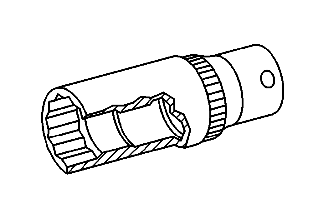
001 589 65 09 00
Socket wrench bit
Powiązane dokumenty
- ah0000p500001a Wskazówki dotyczące zapobiegania uszkodzeniom na skutek zabrudzeń i ciał obcych
- ar0520d6020tsc
- ar0704d0056tsc
- ar0704d0057tsc
- as0000z000201a Niebezpieczeństwo zranienia skóry i oczy na skutek kontaktu z gorącymi lub żarzącymi się przedmiotami
- as0000z001701a Niebezpieczeństwo obrażeńo elementy pojazdu o ostrych krawędziach.
- as1800z000101a Niebezpieczeństwo obrażeń skóry i oczu podczas kontaktu z olejem silnikowym. Niebezpieczeństwo zatrucia wskutek połknięcia oleju silnikowego