
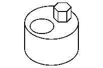


642 589 00 33 00
Riveting tool
651 589 00 40 00
Counterholder
651 589 04 63 00
Assembly inserts
651 589 03 40 00
Hold-down device
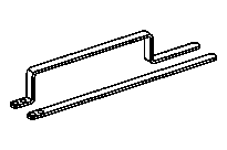

651 589 08 40 00
Counterholder
602 589 00 98 00
Case

The timing case shaft must be covered with clean rag to protect against falling parts before doing work on the timing chain (1). Parts which have nevertheless managed to fall into the timing case recess must be removed.
Engine damage may occur otherwise.
D05.10-1197-01

1 | Insert new riveted link (2) into the ends of the new timing chain (1). |
2 | Turn engine slowly with counterholder at the crankshaft in direction of engine rotation until the new riveted link (2) in the assembly position. |
The new riveted link (2) must be positioned as shown in front of hold-down tool. |
D05.10-1203-11

3 | Prepare separate parts of the special tools. |
The separate parts of the special tools are stored in the case. |
4 | Place assembly insert (3.2) with the digit F12 into the rivet press tool (3) and fix in place with a screw/bolt. |
5 | Insert movable thrust piece (3.1) with digit D14 into the rivet press tool (3). |
6 | Insert new outer link (4) into the thrust piece (3.1). |
Outer link (4) is held magnetically in thrust piece (3.1). |
D05.10-1190-01

1 | Timing chain |
3 | Rivet press tool |
3.2 | Assembly insert |
5 | Thrust spindle |
S05.10-4515-11
7 | Place rivet press tool (3) in such away that the spacer bushing of the assembly insert (3.2) lies on the roll of the timing chain (1). |
Ensure that screw/bolts on rivet element (2) are flush with holes on outer link (4). |
8 | Screw in thrust spindle (5) on rivet press tool (3) until there is firm resistance. |
While screwing in the thrust spindle (5), ensure that pin in rivet link (2) is inserted in holes in the outer mounting link (4). |
9 | Slightly unscrew the thrust spindle (5) and remove rivet press tool (3). |

10 | Turn over movable thrust piece (3.1) with digit D14 on the riveted profile (arrow). |
D05.10-1192-01
3 | Rivet press tool |
5 | Thrust spindle |
S05.10-4515-11
11 | Place rivet press tool (3) exactly above center of rivet element pin (2). |
12 | Tighten thrust spindle (5) on rivet press tool (3) with specified tightening torque. . |
The pins on the rivet element (2) are riveted. |
13 | Slightly unscrew thrust spindle (5), place rivet press tool (3) at another pin on rivet element (2) and rivet other screw/bolt in same way. |

14 | Check rivet (arrows) on the pin; rerivet with rivet press tool (3) if necessary. |
15 | Remove hold-down tool. |
P05.10-2237-01