GF14.40-P-2010P | Component description for the diesel particulate filter | 21.6.04 |
ENGINE 642 in MODEL 203.0 /2
with CODE (474) Particulate filter
up to Model Year 8
ENGINE 642 in MODEL 209.3 /4 with CODE (474) Particulate filter

P49.10-2515-05
Illustrated on Model 203.0
18 Primary catalytic converter
19 Catalytic converter
21 Muffler
114 Diesel particulate filter (DPF)
Location
The DPF is located at the center in the vehicle underfloor.
Task
The diesel particulate filter filters, stores and burns the soot particles that are generated during the combustion process.
Design
The diesel particulate filter consists of a ceramic honeycomb filter body out of silicon carbide, which is coated with rare metal platinum. The passages of the diesel particulate filter are opened alternatively at front and rear and are separated from each other through the porous filter walls of the honeycomb filter body.
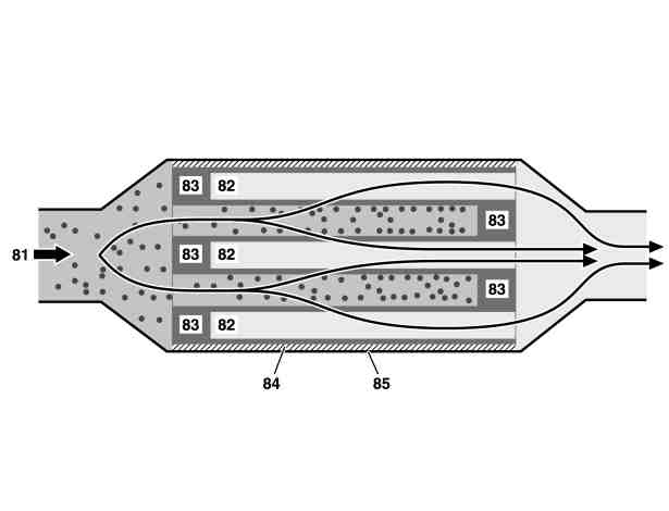
P14.40-2027-06
81 Exhaust gas flow
82 Ceramic monolith
83 Plug
84 Insulation
85 Housing
Function
The unfiltered exhaust gas flows through the porous ceramic honeycomb filter of the DPF.
The soot particles are physically retained in the honeycomb filter body of the DPF. For regeneration of the DPF, the vehicle load of the DPF is determined by the exhaust gas pressure upstream and downstream of the DPF. The signals are evaluated by the differential pressure sensor (DPF) (B28/8) and transmitted to the CDI control unit(N3/9).
Temperatures above 600°C are necessary for soot oxidation which are not obtained during normal operation of the diesel engine. For this purpose, the CDI control unit can take the following measures to increase the exhaust gas temperature:
Intake air throttling
Late injection
Diesel particle filter glowing