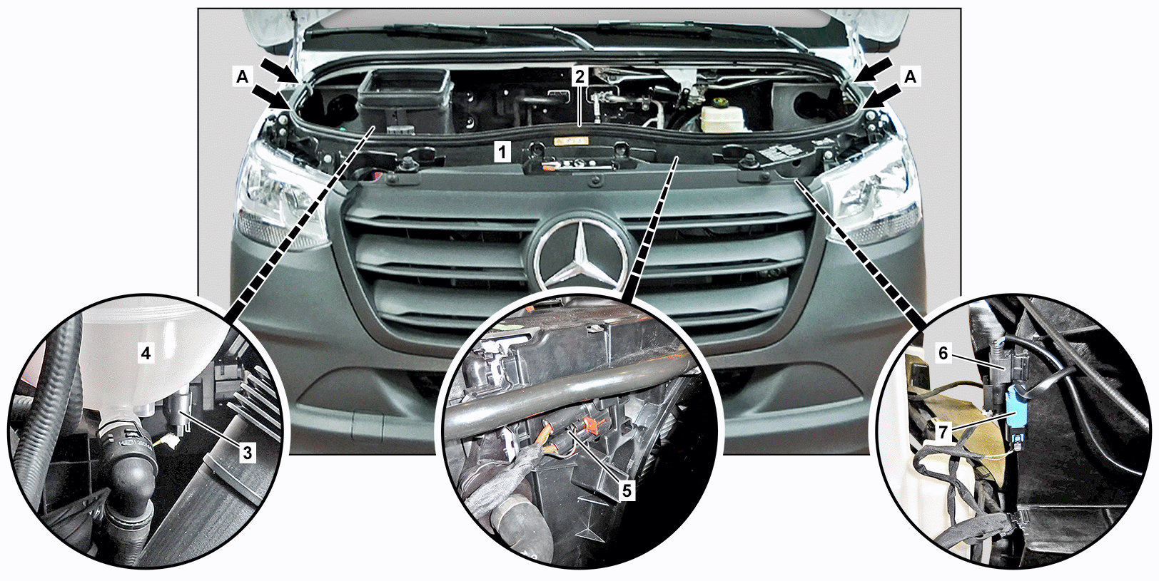
D88.00-A004-79
1 | Top front crossmember | 4 | Coolant expansion reservoir | 6 | Electrical connector | ||
2 | Seal | 5 | Electrical connector | 7 | Electrical connector | ||
3 | Electrical connector |
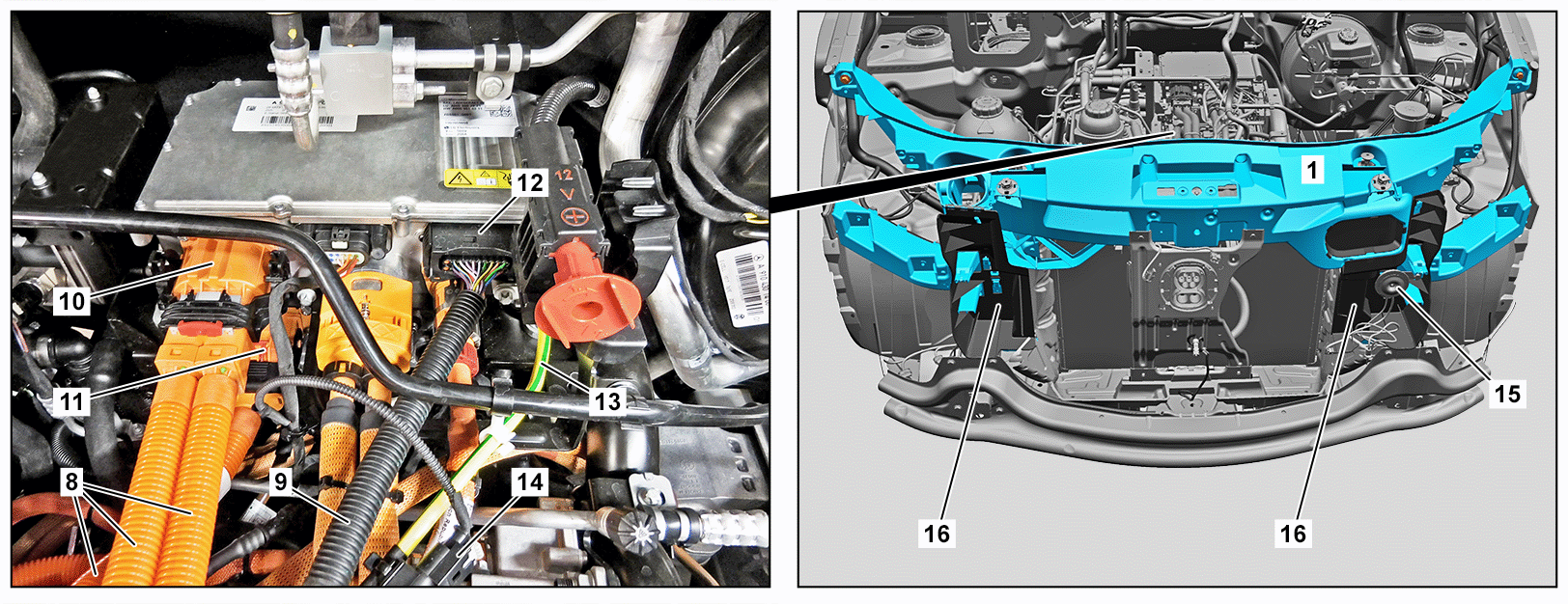
D88.00-A003-78
1 | Top front crossmember | 11 | High-voltage connection | 14 | Electrical connector | ||
8 | High-voltage lines | 12 | Electrical connector | 15 | Signaling horn | ||
9 | Electrical wiring harness | 13 | Electrical line | 16 | Air duct segment | ||
10 | High-voltage connection |
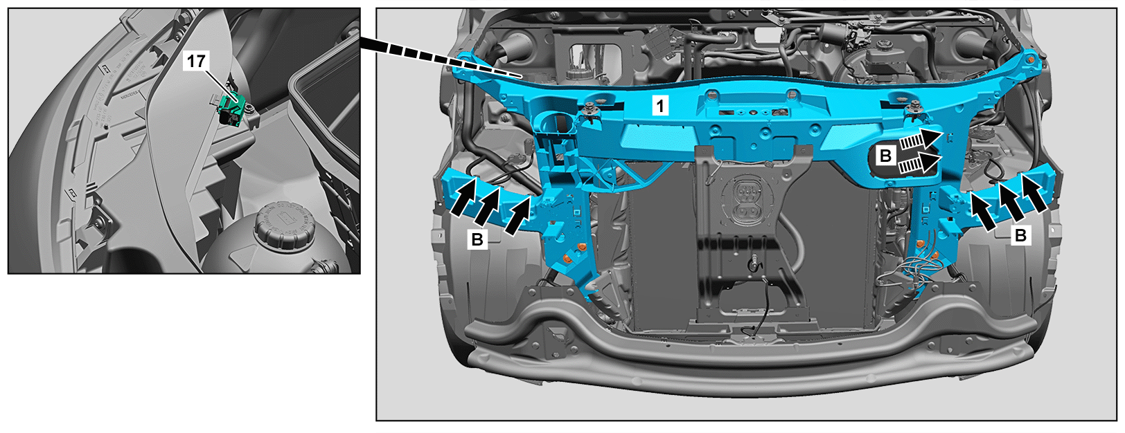
D88.00-A007-78
1 | Top front crossmember | 17 | High-voltage shutoff device |
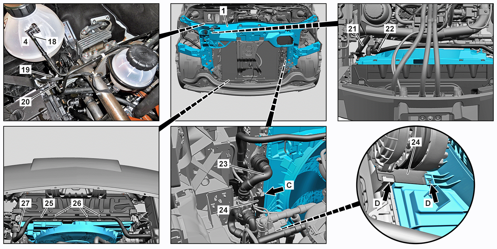
D88.00-A006-79
1 | Top front crossmember | 20 | Coolant hose line | 24 | Bracket | ||
4 | Coolant expansion reservoir | 21 | Coolant hose line | 25 | Coolant line | ||
18 | Coolant hose line | 22 | Coolant line | 26 | Retaining clips | ||
19 | Coolant hose line | 23 | Coolant line | 27 | Connection fitting |
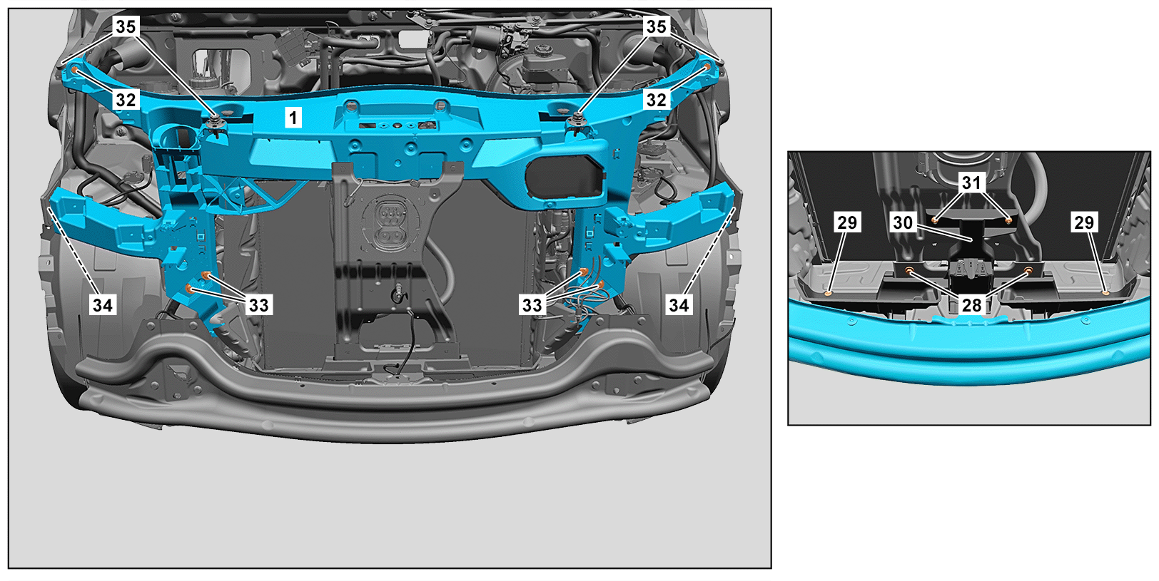
D88.00-A005-79
Shown with code BA3 (Active Brake Assist) |
1 | Top front crossmember | 30 | Bracket | 33 | Bolts | ||
28 | Bolts | 31 | Bolts | 34 | Screw | ||
29 | Expansion rivet | 32 | Screw | 35 | Stop buffer |
Danger | Risk of death when working on component parts and systems with U >= 30 V alternating voltage (AC) or U >= 60 V direct voltage (DC) | Do not touch damaged or defective live component parts and lines or non-insulated electrical connections and lines. | |
Warning | Risk of injury due to fan starting unexpectedly | Do not reach into the rotation or hazard area of the fan. Wear closed and close-fitting work clothes. | |
Warning | Risk of injury to skin and eyes suffering scalding from contact with hot coolantspray. Risk of poisoning from swallowing coolant. | Do not open cooling system unless coolant temperature is below 90 °C. Open cap slowly and release the pressure. Do not pour coolant into beverage containers. | |
Topical note | Notes on avoiding damage through contamination and foreign objects | ||
Topical note | Information on preventing damage to electronic components due to electrostatic discharge | ||
Topical note | General information on handling vehicles with high-voltage on-board electrical system and/or lithium-ion battery and/or gaseous-fuel drive system | ||
| Remove/install | ||
1 | Drain coolant of main circuit. | ||
2 | Drain coolant of the auxiliary circuit. | ||
3 | Remove radiator grille. | ||
4 | Remove the seal (2). | Remove the seal (2) only on the upper longitudinal member (arrow A). | |
5 | Disconnect the electrical connector (3) on the coolant expansion reservoir (4) of the auxiliary circuit. | ||
6 | Disconnect electrical connector (5). | ||
7 | Disconnect electrical connectors (6, 7). | ||
8 | Remove hood catch lower section. | ||
9 | Unhook hood cable at upper front crossmember (1) and position outside of working area. | ||
10 | Remove both front lamp units. | ||
11 | Remove the high-voltage lines (8). | To do so, remove the retaining clips. | |
Installation: Check retaining clips for damage. | |||
Clip remover | |||
If damage is present: | |||
| |||
Replace damaged retaining clips. | |||
12 | Remove the electrical wiring harness (9). | To do this, detach the retaining clip. | |
Installation: Check retaining clips for damage. | |||
Clip remover | |||
If damage is present: | |||
| |||
Replacing retaining clip. | |||
13 | Release and disconnect the high-voltage plug (10). | ||
14 | Release and disconnect high-voltage plug (11). | ||
15 | Separate electrical connector (12). | ||
16 | Remove the electric line (13) at the DC current charge-connection unit and place to one side. | Check ground lines for high-voltage on-board electrical system potential equalization | |
To do this, undo bolt. | |||
Installation: Check the electric line (13). | |||
Screw, potential equalization ground line/protective ground conductor to DC current charge-connection unit | |||
17 | Disconnect electrical connector (14). | ||
18 | Place the high-voltage lines (8), electrical wiring harness (9) and electric line (13) out of the working area. | ||
19 | Remove the horn (15) and place it outside the working area. | ||
20 | Remove the air duct segments (16). | ||
21 | Remove the high-voltage shutoff device (17). | To do this, detach the retaining clip. | |
Installation: Check retaining clips for damage. | |||
Clip remover | |||
If damage is present: | |||
| |||
Replacing retaining clip. | |||
22 | Remove the electrical wiring harnesses on the left and right on the front upper crossmember (1) (arrow B) and place it outside the working area. | Installation: Check retaining clips for damage. | |
Clip remover | |||
If damage is present: | |||
| |||
Replace damaged retaining clips. | |||
23 | Remove the coolant hose lines (18, 19) on the coolant expansion reservoir (4). | ||
Collect coolant which flows out. Plug openings. | |||
Commercially available devices/tools | |||
Record plug | |||
Set of protective covers | |||
24 | Remove the coolant hose line (20) on the cooler. | ||
Collect coolant which flows out. Plug openings. | |||
Commercially available devices/tools | |||
Record plug | |||
25 | Remove the coolant hose line (21) on the cooler. | ||
Collect coolant which flows out. Plug openings. | |||
Commercially available devices/tools | |||
Set of protective covers | |||
26 | Disconnect the coolant line (22) at the separating point. | ||
Collect coolant which flows out. Plug openings. | |||
Commercially available devices/tools | |||
Set of protective covers | |||
27 | Remove the coolant line (23) at the cooler. | ||
Collect coolant which flows out. Plug openings. | |||
Commercially available devices/tools | |||
Set of protective covers | |||
28 | Remove the bracket (24). | To do so, unlock the holder (24) (arrow C) and pull it up and out of the guides (arrow D). | |
29 | Remove the coolant line (25). | To do so, unclip the coolant line (25) from the retaining clamps (26). | |
30 | Remove the connection fitting (27) for the coolant line (25) on the cooler. | ||
Collect coolant which flows out. Plug openings. | |||
Commercially available devices/tools | |||
Set of protective covers | |||
31 | Unscrew the screws (28). | ||
32 | Remove the expansion rivet (29). | Installation: Check the expansion rivet (29) for damage. | |
Clip remover | |||
If damage is present: | |||
| |||
Replace the expansion rivet (29) if damaged. | |||
33 | Remove the holder (30) and place outside the working area. | Model 910 with engine 780.703 | |
To do so, unscrew the screws (31). | |||
34 | remove the upper front crossmember (1) with the radiator. | To do so, unscrew the screws (32, 33, 34). | |
Bolt, crossmember for hood catch to front upper longitudinal member | |||
Bolt, crossmember for hood catch to front upper inner longitudinal member | |||
Bolt, crossmember for hood catch to front longitudinal member | |||
35 | Remove seal (2). | If upper front crossmember (1) is replaced. | |
Installation: | |||
36 | Remove the coolant expansion reservoir (4) from the upper front crossmember (1). | If upper front crossmember (1) is replaced. | |
Long wedge | |||
37 | Remove radiator unit. | If upper front crossmember (1) is replaced. | |
38 | Remove the stop buffers (35). | If upper front crossmember (1) is replaced. | |
39 | Remove the socket for the external power supply. | If upper front crossmember (1) is replaced. | |
40 | Install in the reverse order. |


115 589 03 59 00
Long wedge
001 589 01 91 00
Set of protective covers
452 589 01 63 00
Clip remover
129 589 00 91 00
Record plug
참조 문서
- ah0000p500001a 불순물 및 이물질에 의한 손상 방지 지침
- ah0000z030001a 고전압 차량 전원 시스템 및/또는 리튬 이온 배터리 및/또는 가스 구동 시스템 장착 차량과 개인 보호 장비에 관한 일반 지침
- ah5400p000101a 정전기 방전으로 인한 전자 부품 손상 방지 지침
- ar0850d0022te
- ar0850d0023te
- ar0850d0120te
- ar0850p001801eq 냉각수 호스 커플링 열기, 닫기
- ar4770d0025te
- ar4770d102001te
- ar5435d1556ts 경음기 탈, 장착
- ar8210d4733ts 전방 램프 유닛 탈, 장착
- ar8840d3201ts 엔진 후드 캐치 탈, 장착
- ar8840d4001ts 라디에이터 그릴 탈, 장착
- as0000z003501a U >= 30V 교류(AC) 또는 U >= 60V 직류(DC)를 사용하는 부품 및 시스템 작업 시 생명 위험
- as2000z000101a 뜨거운 냉각수 분출 시 입은 화상에 의한 피부와 안구의 상해 위험 냉각수의 음용으로 인한 중독 위험
- as2040z000101a 팬의 갑작스러운 작동으로 인해 발생할 수 있는 상해 위험