B26.00-A000-09
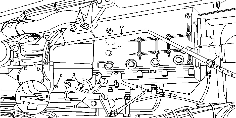
1,2,10 | Pneumatic pipe mounting brackets | 9 | Pneumatic line nut | |
3,6 | Gearbox mounting fastening screws | 11 | Gearbox | |
4,8 | Electric connectors | 12 | Pneumatic tubes | |
5 | Operating lever nut | 13 | Activation lever | |
7 | Transmission to engine carcass fastening screw |
Danger | Risk of fire/risk of explosion due to short circuit and escaping oxyhydrogen gas. Risk of (burn) injury caused by caustic burns to eyes, skin and mucous membranes from battery electrolyte/mist, short circuit and arcing. Risk of poisoning caused by swallowing battery electrolyte or absorption of lead through the skin or body orifices. Risk of death due to voltage U >= 30 V AC and U >= 60 V DC. | No fires, sparks, open flames, or smoking. Wear acid-resistant gloves, clothing, and glasses. Pour battery acid only into suitable and appropriately marked containers. | |
| Remove/install | ||
1 | Disconnect battery ground cable |
| |
Topical note | Notes on battery | ||
2 | Empty the compressed air system | Actuate the valve in the compressed air reservoir. | |
3 | Remove the inspection cover over the transmission (11) | Inspection cover may vary according to bodybuilder. | |
4 | Remove the lower coating | ||
5 | Disconnect the electric wires (4,8) | ||
6 | Remove the pneumatic pipe mounting brackets (1,2,10) | ||
7 | Loosen the pneumatic pipe nuts (9) and remove the pneumatic pipe (12) | ||
8 | Drain the coolant and remove the pipe | ||
Topical note | Notes on coolant | ||
| Type 382.177/178 with transmission 718.853 | ||
9 | Remove the control lever | Transmissions 718.856Operating lever nut | |
10 | Drain oil from transmission | Carry out this service operation only if it is necessary to change the oil or if you disassemble the gearbox. | |
| |||
Transmissions 718.850/856Oil drain plug | |||
Transmissions 718.850/853/856Filler plug | |||
11 | Support the transmission with the proper lifting equipment | Support the engine by the lower part of the coupling housing. The hydraulic equipment must have a supporting surface. | |
12 | Remove transmission shaft | ||
Propeller shaft attachment | |||
13 | Remove the gearbox mounting fastening screws | Type 382.177/178, 384.063 with engine 926.9Fastening bolt of the bearing in the transmission | |
14 | Remove and install the clutch booster of the transmission |
| |
Type 634.011 | |||
It is not necessary to remove the clutch receiving cylinder tubes. | |||
Transmissions 718.850/853/854Sender cylinder attachment | |||
To prevent damages on the pipes: | |||
| |||
Attach the clutch slave cylinder on chassis. | |||
15 | Remove the clutch fork tappet |
| |
Installation: Lock the clutch bearing in the pressure plate safety ring and lock the tappet for engaging into the clutch fork. | |||
Transmissions 718.850/853/854Gearbox fork | |||
16 | Install the lifting equipment to raise the transmission | Use an appropriate equipment. | |
17 | Lift the transmission by the carrying strap until it is contact free with the gearbox mounting | ||
18 | Remove the engine carcass transmission fastening screw (7) | First loosen the upper screws, and then the lower ones. | |
Installation: Do not incline the gearbox with the clutch housing on the engine housing flange. | |||
Transmission 718.85Gearbox to engine | |||
19 | Lift the transmission (11) to free from the engine carcass | Pay attention not to damage the electric wires or the pneumatic tubes. | |
Installation: Mount the clutch bearing on the fork before installing the transmission on the engine. | |||
In case it is difficult to remove the transmission from the engine carcass: | |||
| |||
Use a rubber hammer. | |||
20 | Put long lasting lubricant grease in the drive shaft splined part | Clean the grease surplus which can negatively affect the clutch. | |
Antifriction paste, rubber parts 2.5 kg, DBL 6867.00 | |||
21 | Install in reverse order | ||
22 | Adjust the gearbox controls | ||
23 | Engage successively all the gearbox speeds | In case of difficulties to engage the gears: | |
| |||
Repeat the adjustment procedure. | |||
24 | Check the gearbox oil level | ||
| |||
25 | Check transmission for tightness |
Propeller shaft |
Number | Designation | Model 368.0/1, 384.0/1/2/3, 634.0, 682.0/3, 685.282/284/289/290 | Model 382.0/1, 386.3, 388.0, 693, 694.0, 695, 696 | |||
BA41.10-B-1003-01C | Propeller shaft attachment | Tapped holes terminals (clamps and screws) | ||||
M10x1 | Nm | 65...80 | 65...80 | |||
M12x1,25 | Nm | 115...135 | 115...135 | |||
1/2" | Nm | 160...180 | 160...180 | |||
For flanges | ||||||
M10 | Nm | 60...70 | 70 | |||
M12 | Nm | 115...125 | 125 | |||
M14 | Nm | 140...200 | 185 | |||
M16 | Nm | 280...310 | 275 |
참조 문서
- ah2000n208001a 냉각수 지침
- ah5410p000101a 배터리 관련 지침
- ah5410p000101a
- ap2000b2010xa
- ap2600b2601i
- ar2510b005003ba
- ar2520b0300a
- ar2520b0300xa
- ar4110b0050a
- ar5410b0003a
- as5410z000101a 단락 및 폭발성 기체 유출로 인한 화재/폭발 위험 배터리 전해액/증기, 단락 및 전기 아크에 노출 시 눈, 피부, 점막의 부식으로 인한 화상/상 해 위험 배터리 전해액을 삼키거나 피부