49-7000 Removing and installing exhaust system
Preceding work: Removing and installing engine compartment panel | Operation no. of operation texts and work units or standard texts and flat rates: 49-7000. |
A. Model 107

P49-0023-57
Plug connection, oxygen sensor heating coil (G3/2x1) and plug connection, oxygen sensor signal (G3/2x2) |
in right footwell, below cover plate, separate, plug together. |
Heat shield (2c) | pull off, fit on. Pay attention to installation position. |
Oxygen sensor (G3/2) | unscrew, install. Installation note Coat thread with paste 000 989 88 51. |
Bolts (27) | unscrew, screw in. Take off flame shield (28), fit on (only ). |
Bolts (4) | unscrew, screw in. Replace bolts (4). Tightening torque 25 Nm (reference value). |
Rubber rings (18, 29) | detach, attach. Check whether damaged and worn. |
Front exhaust pipe with front and underflow catalytic converter (2a) or front exhaust pipe with front and centre silencer (2g) | take off, fit on. |
Riveted nuts (1) | at exhaust manifold, remove, install. Knock out riveted nuts with a suitable tool, (e.g. bolt). Installation note Install riveted nuts with cocking bolt |
Carrier (10) | check suitability for reuse, replace if necessary. |
Exhaust system | with engine running, check for leaks. |

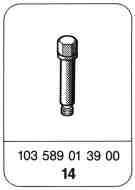
Special tools

Location of oxygen sensor plug connection
G3/2x1 Plug connection, oxygen sensor heating coil
G3/2x2 Plug connection, oxygen sensor signal
P07-2559-13
B. Models 124, 126, 201

Shown on model 124
P49-0024-59
Plug connection, oxygen sensor heating coil (G3/2x1) and plug connection, oxygen sensor signal (G3/2x2) |
in footwell, separate, plug together. |
Heat shield (2c) | pull off, fit on. Pay attention to installation position. |
Oxygen sensor (G3/2) | unscrew, install. Installation note Coat thread with paste 000 989 88 51. Ensure cable is correctly routed. |
Retaining bar (31) with dished springs (32) and self-locking nuts (33) |
take off, fit on.Tightening torque 7 Nm (reference value). Installation note |
Bolts (4) | unscrew, screw in. Replace bolts (4). Tightening torque 25 Nm (reference value). |
Carrier (30) with bolts (11), washers (12), rubber washers (14) and nuts (23) |
Installation note Check parts and replace if necessary. |
Front exhaust pipe with front and underflow catalytic converter (2a) or front exhaust pipe with silencer (2) |
|
Riveted nuts (1) | at exhaust manifold, remove, install. Knock out riveted nuts with suitable tool (e.g. bolt). Installation note Install riveted nuts with cocking bolt |
Exhaust system | with engine running, check for leaks. |
Special tools

Install the dished springs at the retaining bar so that the curved face is always opposite the other (as illustrated).
P49-0022-33

Model 124
G3/2x1 Plug connection, oxygen sensor heating coil
G3/2x2 Plug connection, oxygen sensor signal
P07-2558-13
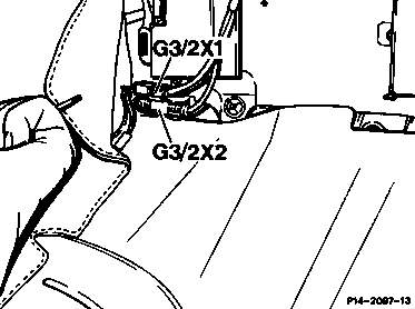
Model 126
G3/2x1 Plug connection, oxygen sensor heating coil
G3/2x2 Plug connection, oxygen sensor signal
P14-2097-13

Model 201
1st version
G3/2x1 Plug connection, oxygen sensor heating coil
G3/2x2 Plug connection, oxygen sensor signal
P07-2135-13A

Model 201
2nd version
G3/2x1 Plug connection, oxygen sensor heating coil
G3/2x2 Plug connection, oxygen sensor signal
P07-5212-13
C. Model 129

P49-5016-59
Plug connection, heated oxygen sensor (G3/2x1) |
Note Slackening union nut=counter-clockwise Tightening union nut=clockwise |
Heat baffle (2c) | pull off, fit on. Pay attention to installation position. |
Oxygen sensor (G3/2) | unscrew, install. Installation note Coat thread with paste 000 989 88 51. |
Self-locking nuts (6a) | unscrew, screw on, replace. |
Carrier (30) with bolts (11), washers (12), rubber washers (14) and nuts (23) |
Installation note |
Threaded plate (6) | check suitability for reuse, replace if necessary. |
Bolts (4) | unscrew, screw in. Replace bolts (4). Tightening torque 23 Nm (reference value). |
Rubber ring (17) | detach, attach. Check for damage and wear. |
Front exhaust pipe with underflow catalytic converter (2d), or front exhaust pipe with front silencer (2b) |
|
Bolt (16) | replace. Tightening torque 25 Nm (reference value). |
Holder (15) | check suitability for reuse. |
Riveted nuts (1) | at exhaust manifold, remove, install. Knock out riveted nuts with suitable tool (e.g. bolt). Installation note Install riveted nuts with cocking bolt |
Exhaust system | with engine running, check for leaks. |
Special tools
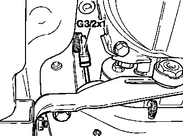
G3/2x1 Plug connection, heated oxygen sensor
P14-2011-13A