41-100 Removal and installation of propeller shaft intermediate bearing and renewing of grooved ball bearing
A. Models 107, 114, 115, 116, 123
Lubricant
Clamp connection | refer to Specifications for Service Products page 266.2 |
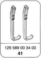
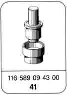

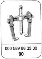
Special tools
Note
The propeller shaft components are individually pre-balanced ex factory. To eliminate a residual unbalance which might still be there, the complete propeller shaft including the flexible couplings, is re-balanced. For this reason, when disassembling the complete propeller shaft (e.g. when changing the propeller shaft intermediate bearing) the individual parts must be marked in relation to each other (if no markings are in place) for reassembly as originally planned.
141-12591
1 Remove propeller shaft (41-050).
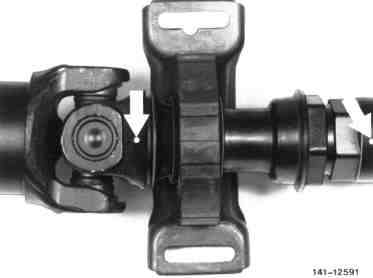
2 On vehicles up to 07/82, mark the individual propeller shaft parts in relation to each other (arrows).
141-12591

3 On vehicles starting 08/82 the front and rear propeller shaft are drawn in relation to each other (arrows).
Note
The identification has in part already been available on propeller shafts prior to 08/82, but has not been taken into consideration during assembly. For this reason, propeller shafts on which the marking is not in accord, must be marked prior to removal and the two parts must be assembled again according to these marks.
141-23660

4 Separate front and rear propeller shaft at the clamp connection.
5 Pull off rubber sleeve (3) via serrations.
Rubber mount with outer V-fold.
R41-5867

6 On vehicles up to 07/82, remove locking ring (5) and remove together with front protective cap (6).
Rubber mount with outer V-fold
R41-5866

7 On vehicles starting 08/82 there is no locking ring but the grooved ball bearing is secured by the protective cap.
141-22993
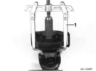
8 On vehicles up to 07/82, pull rubber mount and grooved ball bearing jointly with two-legged puller (1) 000 589 88 33 00 from fork-type joint.
Rubber mount with outer V-fold
141-12587
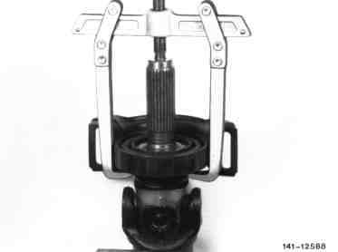
Rubber mount with inner V-fold
141-12588

9 On vehicles starting 08/82, pull rubber mount, grooved ball bearing and protective cap together with two-legged puller and pulling arms 129 589 00 34 00 from fork-type joint.
141-22994

10 Remove rear protective cap on fork-type joint (arrow, installed only on models 107, 116 and 123).

Renewing grooved ball bearing
-------------------------------
11 Press grooved ball bearing (8) out of rubber
mount (7) by means of removing and installing
tool (04) 116 589 09 43 00.
12 Check rubber mount and grooved ball bearing for wear and renew parts, if required.
1413-7384

13 Press grooved ball bearing (8) into rubberized bearing seat up to contact surface (arrows).
Pay attention to correct seat of grooved ball bearing.
1413-7385

Installing propeller shaft intermediate bearing
-------------------------------
14 Insert rear protective cap (on models 107, 116 and 123 only).
15 Press rubber mount on fork-type joint with pressing-on sleeve (3) 126 589 03 15 00, while paying attention to correct location of V-fold:
R41-5785

The V-fold of rubber mount on models 107 and 116 of 1st version should point in driving direction.
Models 107, 116
1 Front propeller shaft
2 Rear propeller shaft
3 Clamping nut
4 Rubber sleeve
5 Locking ring
6 Protective cap
7 Propeller shaft intermediate bearing
8 Grooved ball bearing
9 Fork-type joint
15 Universal joint star with needle bearing and bushings
16 Frame floor
17 Propeller shaft tunnel
Z413-4333

On models 114 and 115 with 2-piece propeller shaft, the V-fold should point opposite to driving direction toward the rear.
On 3-piece propeller shaft the V-fold of front rubber mount should point in driving direction and that of rear rubber mount opposite to driving direction.
Models 114, 115
1 Front propeller shaft
2 Rear propeller shaft
3 Clamping nut
4 Rubber sleeve
5 Locking ring
6 Protective cap
7 Propeller shaft intermediate bearing
8 Grooved ball bearing
9 Fork-type joint
15 Universal joint star with needle bearing and bushings
16 Frame floor
17 Propeller shaft tunnel
Z413-4630

Models 107, 116 of 2nd version and model 123 have a rubber mount with inner V-fold. Install rubber mount in such a manner that the inner V-fold points toward universal joint.
Models 107, 116 2nd version and 123
1 Front propeller shaft
2 Rear propeller shaft
3 Clamping nut
4 Rubber sleeve
5 Locking ring
6 Protective cap
7 Propeller shaft intermediate bearing
8 Grooved ball bearing
9 Fork-type joint
15 Universal joint star with needle bearing and bushings
16 Frame floor
17 Propeller shaft tunnel
1413-6639
16 On vehicles up to 07/82, attach front protective cap.
17 Insert locking ring (5) into groove of fork-type joint in such a manner that the protective cap rests against bearing inner race.
The inner hump of locking ring points toward protective cap.
R41-5866

18 On vehicles starting 08/82 mount self-locking protective cap with pressing-on sleeve 126 589 03 15 00 making sure that the protective cap rests against grooved ball bearing (cutout in Fig.).
Use pressed-on protective cap only once.
1413-10704
19 Pull rubber sleeve (3) over splining of fork-type joint. Make sure that the rubber sleeve is correctly seated on small diameter.
R41-5867
20 Coat spline shaft profile with the specified grease (refer to Specifications for Service Products page 266.2).
21 On vehicles up to 08/82 plug front and rear propeller shaft together as shown.
141-12591
22 Vehicles starting 08/82 are provided with an identifying mark on front and rear propeller shaft. On front propeller shaft is a hump and on fork-type joint of rear propeller shaft there are two arrow-like humps (arrows). The hump of the front propeller shaft should be located between the two arrows on the fork-type joint (arrows).
23 Install propeller shaft (41-050).
141-23660
B. Model 126

P41-0006-33
Propeller shaft | remove and install (41-050). |
Front and rear propeller shaft (1,2) | separate, plug together (item 2). |
Rubber sleeve (4) | pull on and off (item 3). |
Rubber mount (7) with grooved ball bearing (8) and protective cap (6) |
pull off, press on, remove locking ring (5) on vehicles up to 07/82. (items 4 to 7). |
Rear protective cap (6a) | remove, plug on (item 8). |
Grooved ball bearing (8) | press out of and in rubber mount (7), check and renew if required. 116 589 09 43 00 (items 9 to 11). |
Spline shaft profile (28) | grease with specified grease (refer to Specifications for Service Products page 266.2). |
Special tools
1 Remove propeller shaft (41-050).
2 Separate front and rear propeller shaft at clamp connection.
Note
On vehicles starting 08/82 the front and rear propeller shaft are shown in relation to each other (arrows).
The propeller shaft components are individually pre-balanced ex factory. To eliminate a residual unbalance which might still be there, the complete propeller shaft including the flexible couplings, is re-balanced. For this reason, when disassembling the complete propeller shaft (e.g. when changing the propeller shaft intermediate bearing) the individual parts must be marked in relation to each other (if no markings are in place) for reassembly as originally planned.
141-23660
On vehicles up to 07/82, mark the individual propeller shaft parts in relation to each other (arrows).
Installation note
Grease spline shaft profile with specified grease (refer to Specifications for Service Products page 266.2).
141-12591
3 Pull off rubber sleeve (3) via serrations.
Installation note
Pay attention to correct seat of rubber sleeve on small diameter.
R41-5867
4 On vehicles up to 07/82, pull rubber mount
and grooved ball bearing together with two-
legged puller 000 589 88 33 00 from fork-type
joint.
141-12588
Note
On vehicles up to 07/82, remove locking ring (5)
and remove together with front protective
cap (6).
Installation note
Insert locking ring (5) into groove of fork-type joint in such a manner that the protective cap rests against bearing inner race.
The inner hump of the locking ring points toward protective cap.
R41-5866
5 On vehicles starting 08/82, pull rubber
mount, grooved ball bearing and protective cap
together from fork-type joint by means of two-
legged puller 000 589 88 33 00 and pulling arms
129 589 00 34 00 from fork-type joint.
Note
On vehicles starting 08/82, the grooved ball bearing is secured by the protective cap.
141-22994
Installation note
Press rubber mount by means of pressing-on sleeve (3) 126 589 03 15 00 onto fork-type joint, while paying attention to correct location of V-fold.
R41-5785
6 Install rubber mount with inner V-fold. Install rubber mount in such a manner that the inner
V-fold points toward universal joint.
1st version up to 07/82
1 Front propeller shaft
2 Rear propeller shaft
3 Clamping nut
4 Rubber sleeve
5 Locking ring
6 Protective cap
7 Propeller shaft intermediate bearing
8 Grooved ball bearing
9 Fork-type joint
15 Universal joint star with needle bearing and bushings
16 Frame floor
17 Propeller shaft tunnel
1413-6639
7 Mount self-locking protective cap (on vehicles starting 08/82) with pressing-on sleeve 126 589 03 15 00 making sure that the protective cap rests against grooved ball bearing (8) (cutout in Fig.).
Use pressed-on protective cap only once.
1413-10704
8 Remove rear protective cap (arrow) from fork-type joint.
Renewing grooved ball bearing
-------------------------------
9 Press grooved ball bearing (8) with removing and pressing-in tool (04) 116 589 09 43 00 out of rubber mount (7).
10 Check rubber mount and grooved ball bearing for wear and renew parts, if required.
1413-7384
11 Press grooved ball bearing (8) into rubberized bearing seat up to contact surface (arrows).
Note
Pay attention to correct seat of grooved ball bearing.
12 For further installation proceed vice versa starting at item 8.
1413-7385
C. Models 124, 129, 201

P41-0007-33
Propeller shaft | remove and install (41-050). |
Front and rear propeller shaft (1, 2) | separate, plug together (item 1). |
Rubber sleeve (4) | pull on and off (item 3). |
Rubber mount (7) with grooved ball bearing (8) |
pull off, press on. 126 589 03 15 00 (items 4, 5). |
Rear protective cap (6a) | remove, plug on (item 6). |
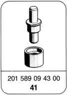
Grooved ball bearing (8) | press out of and into rubber mount (7), check and renew parts if required. Pressing-out, pressing-in tool 201 589 09 43 00 or 116 589 09 43 00 (items 7 to 9). |
Spline shaft profile (28) | grease with specified grease (refer to Specifications for Service Products page 266.2). |

Special tools
1 Remove propeller shaft (41-050).
2 Separate front and rear propeller shaft at clamp connection.
Installation note
The front and rear propeller shaft are correctly plugged together when the hump of the front propeller shaft is located between the two arrows of the rear propeller shaft (arrow). Coat spline shaft profile with specified grease.
141-23660

3 Pull off rubber sleeve (4) via serrations.
Installation note
Pay attention to correct seat of rubber sleeve on small diameter.
141-24704
4 Pull rubber mount with grooved ball bearing
and protective cap jointly from fork-type joint by
means of two-legged puller 000 589 88 33 00
and pulling arms 129 589 00 34 00
141-22994
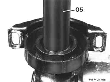
Installation note
Press rubber mount on fork-type joint by means
of pressing-on sleeve (05) 201 589 07 15 00 or
126 589 03 15 00, paying attention to correct
location of V-fold.
141-24705

5 Mount self-locking protective cap (6) with pressing-on sleeve (05) 201 589 07 15 00, while making sure that the protective cap rests against grooved ball bearing.
Use pressed-on protective cap only once.
1413-11022/1
6 Remove rear protective cap on fork-type joint (arrow).

Renewing grooved ball bearing
-------------------------------
7 Press grooved ball bearing (8) with removing
and pressing-in tool (04) 201 589 09 43 00 out
of rubber mount (7) for small grooved ball
bearing and 126 589 09 43 00 for large grooved
ball bearing.
8 Check rubber mount and grooved ball bearing for wear and renew parts, if required
1413-11162/1

9 Press grooved ball bearing (8) into rubberized bearing seat up to contact surface (arrows).
Note
Pay attention to correct seat of grooved ball bearing.
10 For further installation proceed vice versa starting at item 6.
1413-11161
Documenti citati
- bb0040p026602a Grassi lubrificanti di lunga durata (classe NLGI 2)
- ra4100107b050x
- ra4100107c050x
- ra4100107pr00x
- ra4100107ta00x