20-330 Magnetic fan coupling

Note
Engine 601 have a temperature-controlled electromagnetic fan coupling.
This is switched in and switched off by a 100 °C temperature switch (S25/1) which is screwed into the outlet connection.
The electromagnetic fan coupling is maintenance-free.
Design of the electromagnetic fan coupling
The magnet body (347) is attached to the magnet carrier (348) with 3 nuts (349).
The magnet carrier is bonded to the coolant pump housing and does not need to be pulled off.
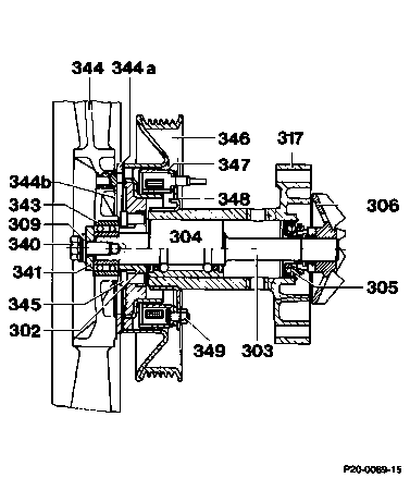
302 Flange
303 Shaft
304 Bearing
305 Cassette seal
306 Impeller
309 Tensioning plate
317 Coolant pump housing
340 Collar bolt
341 Washer
343 Bearing
344 Fan
344a Armature
344b Leaf spring
345 Hexagon socket screw M612
346 Belt pulley
347 Magnet body
348 Magnet carrier
349 Hexagon nut

The electric cable is connected to the magnet body (347) via the coupling (arrow).

The belt pulley (346) is fitted on the coolant pump shaft ahead of the magnet body.
The belt pulley (346) is screwed to the flange of the coolant pump with 4 hexagon socket screws (345) or torx screws.
Function
-------------------------------
The fan cuts in only if the ignition is switched on and the coolant is at a temperature above 98 - 102 °C.
Voltage exists constantly at the magnet body (347) through fuse no. 10 terminal 15
(1st version).
Below a coolant temperature of 98 - 102 °C the fan is switched off and only rotates as a result of the air stream when the vehicle is moving or the bearing friction.
A negative voltage is applied by the temperature switch in the outlet connection no later than a coolant temperature of 102 °C.
The armature (344a) is attracted by the magnet body (347) and presses against the face of the belt pulley (346).
The fan is now rigidly connected to the belt pulley and rotates in line with the coolant pump speed.
If the coolant temperature drops below 98 -
93 °C, the temperature switch opens and the armature is lifted off the belt pulley (346) by the leaf springs (344b).
On vehicles with air conditioning, the fan is engaged and the electric auxiliary fan by means of a double contact relay which is activated by the 52 °C temperature switch at the fluid reservoir.
If the air conditioning is switched off, the 100 °C temperature switch at the outlet connection again performs the tasks of engaging or disengaging the fan.
The armature (344a) and the ball bearing (343) are fitted to or in the fan.
The ball bearing is sealed on both sides with cover plates.

Fan
-------------------------------
The fan sits on a stub end on the coolant pump bearing and is attached with a collar bolt
M818 (engine 601 only).
The fan (A) has 6 blades and a diameter of
380 mm.
On vehicles with air conditioning, the fan (B) has 5 blades and a diameter of 430 mm.

Modification to electromagnetic coupling Model 201
Effective 10/84 a modified electrical centre is installed. As a result, the electromagnetic coupling is operated by a positive voltage through a 2-pin temperature switch (S25/1) (previously negative voltage).

On vehicles with air conditioning positive is connected through a relay even after the pressure switch (14) closes.
Note
After stocks of the previous electrical centre have been used up, only the modified version will be supplied. See Group 54 for conversion instructions.