01-015 Checking cylinders for leaks
Operation no. of operation texts and work units or standard texts and flat rates 01-1300 |

P01-0224-57
Engine | warm up to operating temperature |
Nozzle holders (4) | remove, install (07-230). |
Engine 602.982 (DELA): glow plugs | remove, install (AR15.20-4111C). |
Coolant expansion tank (1) | Open cap (2) on coolant expansion tank only at coolant temperatures below 90°C. Unscrew filler cap (2), screw on. Top up coolant if necessary (steps 4 - 5). |
Air cleaner on naturally aspirated engines (6) |
take off air filter cap, fit on (step 6). |
Oil filler cap (5) | unscrew, screw on. |
Engine | position piston of cylinder to be tested to ignition TDC. Connect cylinder leak tester and calibrate (steps 9 - 12). |
Cylinder | determine pressure loss (steps 13 - 14). Note Check other cylinders in firing order. |
Permissible pressure loss
Total, engine | max. 25 % |
Valves and cylinder head gasket | max. 10 % |
Piston rings | max. 20 % |
Tightening torques Nm
Union nuts on injection lines (reference value) | 10 - 20 |
Nozzle holders for vertical injection | 70+10 |
Nozzle holders for oblique injection | 70+10 |
Glow plug | 20 |
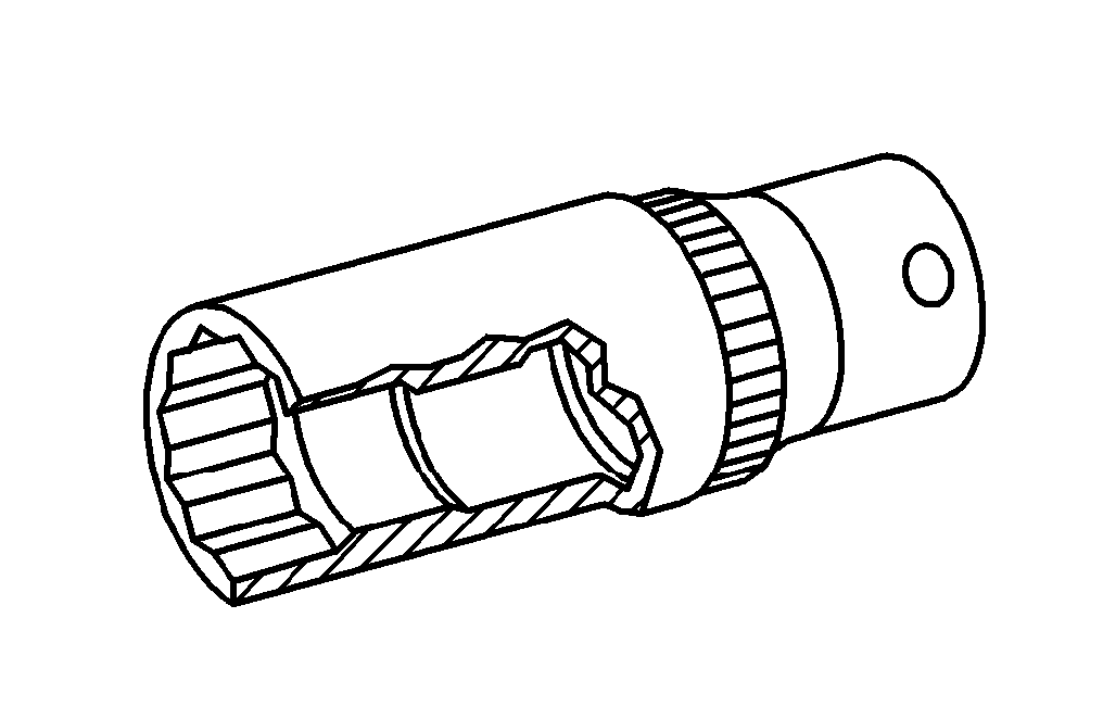

Special tools
001 589 65 09 00
602 589 06 63 00
Commercially available tools and testers
Designation | e.g. Make | Order no. |
Cylinder leak tester | Bosch | EFAW 210 A |
Adapters and connectors | Bosch | 1 687 010 016 |
Testing
-------------------------------
1 Warm engine up to operating temperature (approx. 80°C).
2 Remove all nozzle holders (07-230).
3 Engine 602.982: remove glow plugs (AR15.20-4111C).
Open cap on coolant expansion tank only at coolant temperatures below 90°C.
4 Screw off cap on coolant expansion tank.
5 Check coolant level in coolant expansion tank and add, if required.
6 Open retaining strap on air cleaner cover on naturally aspirated engines or screw out hex. head bolts on air cleaner cap on Turbo-engines, remove air cleaner cap and take out filter cartridge.
7 Screw off oil filler cap.
8 Move piston in cylinder to be checked to TDC, ignition stroke.

9 Screw appropriate adapter (01) with straight or angular connector (02) into precombustion chamber of cylinder to be checked.
10 Engine 602.982 (DELA): insert connector 602 589 06 63 00 with angled connection piece (02) into the glow plug bore of the cylinder to be tested.
P01-2241-13
11 Calibrate cylinder leak tester and fit connection hose (03) of tester onto the connection piece (02).
12 Pressurize cylinder with compressed air and determine any pressure loss at the tester.
P01-2241-13
13 If pressure loss exists, determine cause; check by listening at cylinder head gasket, air intake area, exhaust, oil filler opening and prechamber or glow plug bore of the cylinder and adjacent cylinders and check coolant in coolant expansion reservoir for air bubbles.
Note
If pressure loss is present and air lost through the oil filler cap, the possible causes can be limited by spraying engine oil on the piston crown of the cylinder being tested. The oil seals the gap between the piston and cylinder. If pressure loss is no longer present for a short time, the cause is in all probability the piston, piston rings or cylinder running surface.
The position of the piston ring gaps can result in incorrect determination of the cause. If it is suspected that the pressure loss results from the piston ring gaps being positioned directly above one another, completely assemble engine and repeat test after operating engine for a short time.

14 Conduct the test of the remaining cylinders in the firing order of the engine.
Ignition sequence, engine 601
P01-0116-13

Ignition sequence, engine 602
P01-0118-13

Ignition sequence, engine 603
P01-0117-13
15 Installation is performed in the reverse order.
Documenti citati
- ar1520p4111c Smontare, montare le candelette ad incandescenza
- ra0100601pr00x
- ra0100601ta00x
- ra07016010230x