Valido per: Model 958.0/1 with front axle 733.894/895 Model 958.184/186 with front axle 733.861 Model 958.2 with front axle 739.390 Model 958.2/4 with front axle 739.392 Model 958.260/264 with front axle 739.391 Model 958.43/44/45/46 with front axle 739.390 Model 958.471/472/478 with front axle 739.391 Model 958.472 with front axle 739.412
Valido anche per motori/cambi: 733 861, 733 894, 733 895, 739 390, 739 391, 739 392, 739 412
AR40.20-B-0322-08TA
Measure camber
Model
958.0/1 with front axle 733.894/895
Model
958.184/186 with front axle 733.861
Model
958.2 with front axle 739.390
Model
958.2/4 with front axle 739.392
Model
958.260/264 with front axle 739.391
Model
958.43/44/45/46 with front axle 739.390
Model
958.471/472/478 with front axle 739.391
Model
958.472 with front axle 739.412
Modification notes
18.06.2019
Camber
BE40.20-B-1001-11G
25.06.2019
Câmber
BE40.20-B-1001-11G
01.07.2019
Camber
BE40.20-B-1001-11G
Steering geometry
Number
Designation
Vehicles 934.2, 938.1, 958.2/4 with front axle 739.392
Vehicles 958.184/186 with front axle 733.861
BE40.20-B-1001-11G
Camber
left hand side
°
0° 30' (30')
1° (30')
right hand side
°
0° 30' (30')
1° (30')
Steering geometry
Number
Designation
Vehicles 958.20/43 4X2 with front axle 739.390
Vehicles 958.25/44/46 6X2 with front axle 739.390
BE40.20-B-1001-11G
Camber
left hand side
°
0° 30' (30')
0° 30' (30')
right hand side
°
0° 30' (30')
0° 30' (30')
Steering geometry
Number
Designation
Vehicles 958.45 6X4 with front axle 739.390
Vehicles 958.260/264 6X4 with front axle 739.391
BE40.20-B-1001-11G
Camber
left hand side
°
0° 30' (30')
1° (30')
right hand side
°
0°15' (30')
1° (30')
Steering geometry
Number
Designation
Vehicle 958.472 6X4 with front axle 739.412
Vehicles 958.471/472/478 6X4 with front axle 739.391
BE40.20-B-1001-11G
Camber
left hand side
°
1° (30')
1° (30')
right hand side
°
1° (30')
1° (30')
Steering geometry
Number
Designation
Vehicles 958.03/07/09 with front axle 733.894/895
BE40.20-B-1001-11G
Camber
left hand side
°
1° (30')
right hand side
°
1° (30')
1
Position the projector (5) on the projector support (4).
2
Put the projector (5) in the horizontal in the longitudinal direction and tighten the wing screw (16).
3
Turn the turning button (29) until the level (30) is centered.
W40.20-0032-01
4
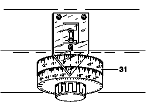
Read the value indicated on the scale disc for camber measurement (31).
The scale disc for camber measuring (31) is divided in the measuring fields "positive camber" and "negative camber". The measuring field "positive camber" reaches from 0 to +8°. The measuring field "negative camber" reaches from 0 to -4°. One division on the scaled disc represents 10'.
5
Record the measuring value on the alignment form.
6
Carry out the camber measurement in the other front axle wheel the same way.