Vehicles 634.011/012/014/081 with front axle 739.386/397
Vehicles 384.061/069
BE40.20-B-1001-11B
Camber
°
1° (30')
1° (30')
Steering geometry
Number
Designation
Vehicles 384.071/074/075/076/078
Vehicles 382.153/154/157/176/177/178/182/185/188
BE40.20-B-1001-11B
Camber
°
1° (30')
1° (30')
Steering geometry
Number
Designation
Vehicles 368.002/004/006 with front axle 732.797
Vehicles 368.100/104/106 with front axle 732.796
BE40.20-B-1001-11B
Camber
°
1° (30')
1° (30')
Steering geometry
Number
Designation
Vehicle 384.067 with front axle 732.797
Vehicles 368.002/004 with front axle 739.916
BE40.20-B-1001-11B
Camber
°
1° (30')
0,25° (30')
Steering geometry
Number
Designation
Vehicles 368.100/104 with front axle 739.916
BE40.20-B-1001-11B
Camber
°
0,25° (30')
The camber measuring procedure depends on the equipment. Refer to the operating manual of the respective equipment to be utilized. In vehicles with two steering front axles, camber measurement occurs the same way on both axles.
1
Position the projector (5) on its support (4)
2
Put the projector (5) in the horizontal in the longitudinal direction and tighten the butterfly screw (16)
3
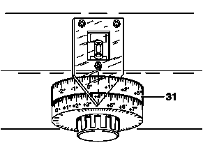
Turn the rotating button (29) until level (30) is centered
W40.20-0032-01
4
Read out the indicated value on the camber measuring scale ring (31)
The camber measuring scale ring (31) is divided in two fields: "Positive camber" and "negative camber". The "positive camber" measuring field ranges from 0 to +8º. The "negative camber" measuring field ranges from 0 to -4º. One division on the scale ring corresponds to 10'.
5
Record the measuring value on the alignment form
6
Carry out the camber measurement on the front axle opposite wheel the same way .