

D26.50-0027-01
D26.50-0028-01
1 Secure the gearbox secondary shaft in a vise with the fixture protected so that the actuation side is placed upward.
2 Remove the lock-ring (45) and the thrust washer (44).
3 Remove the 5th gear shaft (43) and the needle bearing (42).


D26.50-0123-01
D26.50-0030-01
4 Remove the synchronizer taper (46) and the synchronizing ring (41).
5 Remove the lock-ring (40).


D26.50-0124-02
D26.50-0127-02
6 Remove the reverse gear shaft together with the sliding sleeve from the synchronizer body (33 to 39).
7 Remove the needle bearing (32).
8 If necessary, separate the sliding sleeve (35) from the synchronizing body (39) and remove the sliding pads (36), the pressure springs (38) and the spheres (37).
The spheres are under the spring pressure. Cover with a the synchronizing assembling with a proper cloth during the disassembling.

D26.50-0012-01
9 Invert the position of the gearbox secondary shaft.
10 Remove the lock-ring (4).


D26.50-0128-02
D26.50-0129-02
11 Remove the 3rd gear shaft together with the synchronizer taper, the synchronizing ring, the synchronizer body and the sliding sleeve (5 to 11 and 47).
12 Remove the needle bearing (12).
13 If necessary, separate the sliding sleeve (5) from the synchronizing body (9) and remove the sliding pads (6), the pressure springs (8) and the spheres (7).
The spheres and the sliding pads are under the spring pressure. Cover with a the synchronizing assembling with a proper cloth during the disassembling.

D26.50-0017-01
14 Remove the lock-ring (13).

D26.50-0120-03
15 Remove the 2nd gear shaft (15) together with the thrust washer (14).
If necessary, use a puller Apply the puller in the protrusion to the 2nd gear shaft camshaft toothed.
16 Remove the sleeve from the needle bearing (16).

D26.50-0020-01
D26.50-0021-01
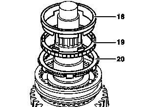
17 Remove the synchronizer taper (18) and the synchronizing ring (19) and the synchronizing tapper (20).
18 Remove the lock-ring (17).


D26.50-0121-03
D26.50-0122-03
19 Remove the 1st gear shaft with all the components id (21 to 29).
Use a puller .
20 Remove the sleeve from the needle bearing (30).
21 If necessary, separate the sliding sleeve (21) from the synchronizing body (25) and remove the sliding pads (24), the pressure springs (23) and the spheres (22).
The spheres and the sliding pads are under the spring pressure. Cover with a the synchronizing assembling with a proper cloth during the disassembling.