
M139, view of engine from front right |
P01.10-A072-76
Introduction
The new engine M139 in the Mercedes-AMG A 45 and A 45 S models is a laterally installed in-line 4-cylinder spark-ignition engine with combined direct injection/intake manifold injection.
With a displacement of 2.0 liters, it will be available in 2 output levels: 285 kW and 310 kW.
Due to the fact that the engine is installed laterally, the exhaust gas turbocharger and exhaust manifold are located at the rear, on the side of the bulkhead to the vehicle interior, as seen in the direction of travel. The intake system is located at the front. This layout allows a flat and aerodynamically beneficial front design and improves the air flow on both the intake and exhaust sides.
Overview of other new features
Section cooling with 3 cooling circuits
Engine management
CAMTRONIC at exhaust side
Timing assembly located at rear with camshaft positioner
Valve train with roller-type rocker arm
Combined direct and intake manifold injection
Charged by twin-scroll exhaust gas turbocharger located at rear and boost pressure control flap actuator
Crankcase ventilation system integrated in charge-air distributor
Belt-in-oil for oil pump operation
Exhaust system
Section cooling with 3 cooling circuits
Since the engine's output was increased to up to 310 kW, further measures on the engine cooling system were necessary. The aim was to achieve optimum cooling for maximum output by implementing consumption-reducing measures.
Section cooling that consists of three independent circuits is used in engine M139:
High-temperature circuit
Medium-temperature circuit
Low-temperature circuit
The powertrain control unit (N127) regulates all cooling circuits. It evaluates the data of the temperature sensors and actuates the electric coolant pump in the high-temperature circuit and the regulation valve if necessary. Mechanical thermostats are installed in the high- and medium-temperature circuits.
With section cooling, the high-temperature circuit ensures that the crankcase is cooled. To do this, the coolant is circulated by an electric coolant pump in the high-temperature circuit. Due to the increase of the component part protection temperature of the crankcase to 125 °C, the thermostat in the high-temperature circuit only opens as from a temperature of approx. 115 °C and is completely open as from approx. 120 °C. This measure helps to reduce waste heat in all circuits and optimize heat dissipation on the vehicle side.
The medium-temperature circuit cools the cylinder head. To do this, the coolant is circulated by a mechanical coolant pump. The thermostat remains closed up to a coolant temperature of approx. 73 °C and is completely open as from approx. 80 °C. A regulation valve that regulates the engine oil water heat exchanger flow is also installed in the medium-temperature circuit. It regulates the oil temperature to 110 °C. The overall coolant volume flow rate in the medium-temperature circuit was increased to 370 l/min at the cylinder head, which optimizes heat dissipation.
The low-temperature circuit is an uncontrolled circuit; its operating temperature is between 50 and 70 °C. The coolant is circulated by an electric coolant pump. The charge air is cooled indirectly via the coolant in the low-temperature circuit.
Further advantages of section cooling:
Effective cylinder head cooling
Improved fuel economy due to:
Use of low-friction oil
Increased cylinder wall temperature
Standing coolant in crankshaft housing during warm-up
Reduction of coolant volume flow rate in crankshaft housing
Engine oil heated by medium-temperature circuit and standing coolant in high-temperature circuit
Oil cooling as required
Transmission oil is heated during warm-up
The A 45 S model is equipped with a refrigerant/water heat exchanger in the low-temperature circuit, which can provide additional charge air cooling performance, especially during use on race tracks at high outside temperatures.
Further information can be found in the function description "Basic heat management function" GF07.10-P-9900A.
When a service or repair operation is performed in the high-temperature and/or medium-temperature circuits, both circuits must be drained and vacuum-filled again. Please observe the check and repair work operation step "Pour in coolant and bleed cooling system" AR20.00-P-1142-04A.
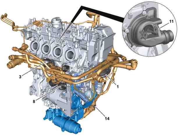
Engine cooling for engine M139, component parts |
1 | High-temperature circuit coolant pump |
3 | High-temperature circuit coolant thermostat |
8 | Medium-temperature circuit coolant pump |
11 | Medium-temperature circuit coolant thermostat |
14 | Medium-temperature circuit regulation valve |
P20.00-A021-76
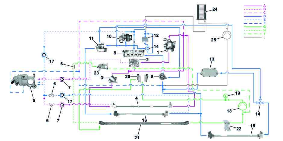
P20.00-A040-79
Schematic diagram of coolant circuit |
1 | High-temperature circuit coolant pump | 13 | Transmission oil heat exchanger | 25 | Heating circuit coolant pump | ||
2 | Crankcase | 14 | Medium-temperature circuit regulation valve | A | High-temperature circuit | ||
3 | High-temperature circuit coolant thermostat | 15 | Medium-temperature circuit cooler | B | High-temperature circuit ventilation | ||
4 | High-temperature circuit cooler | 16 | Medium-temperature circuit additional cooler | C | High-temperature circuit filler line | ||
5 | Expansion reservoir | 17 | Medium-temperature circuit regulation valve | D | Medium-temperature circuit | ||
6 | Restrictor | 18 | Low-temperature circuit coolant pump | E | Medium-temperature circuit ventilation | ||
7 | High-temperature circuit regulation valve | 19 | Low-temperature circuit temperature sensor | F | Medium-temperature circuit filler line | ||
8 | Medium-temperature circuit coolant pump | 20 | Charge air cooler | G | Low-temperature circuit | ||
9 | Cylinder head | 21 | Radiator low-temperature circuit | H | Low-temperature circuit ventilation | ||
10 | Turbocharger | 22 | Evaporator (S model only) | I | Low-temperature circuit filler line | ||
11 | Medium-temperature circuit coolant thermostat | 23 | Low-temperature circuit expansion reservoir | J | Heating circuit | ||
12 | Engine oil heat exchanger | 24 | Heating circuit heat exchanger |
Engine management
CAMTRONIC at exhaust side
All output variants of the M139 are equipped with the exhaust-side CAMTRONIC.
The optimum cam contour can be set depending on the engine operation and the driver's request. Two different elevation options are available; all exhaust valves are activated with the same elevation. The switch-over is performed by cam segments that can be shifted axially, and energy-efficient switching via electric actuators. The actuators require energy only during the shift operation and are then de-energized.
The following advantages result through this:
Faster boost pressure buildup in dynamic lower partial-load operation
Greater exhaust gas dynamics in dynamic driving mode (lower partial load)
Improved response time of exhaust gas turbocharger
Reduction of charge change losses
Comfort and consumption optimization in stationary lower partial-load operation
Phase setter for intake and exhaust
In addition, the timings of the intake and exhaust camshafts can each be regulated in phases independently from one another using a setter. To do this, the camshafts are twisted in relation to the crankshaft, and the closing of the exhaust and opening of the intake are changed. The valve overlap can be varied. In case of a large valve overlap, the exhaust closes late and the intake opens early.
Large valve overlaps result at partial load in a reduction of the combustion temperature and a reduced formation of nitrogen oxides (NOx). At the exhaust side, the intake of the exhaust gases again allows for the effect of an internal exhaust gas recirculation.
In case of a small valve overlap, the exhaust closes early and the intake opens late. Small valve overlaps prevent in idle state air from overflowing into the exhaust port and exhaust gases from overflowing into the intake port. At full-load operation, a subsequent flowing of the air results in a recharging effect at higher torque.
Further information on the engine timing can be found in the function description "Basic valve timing function" GF05.00-P-1001A.
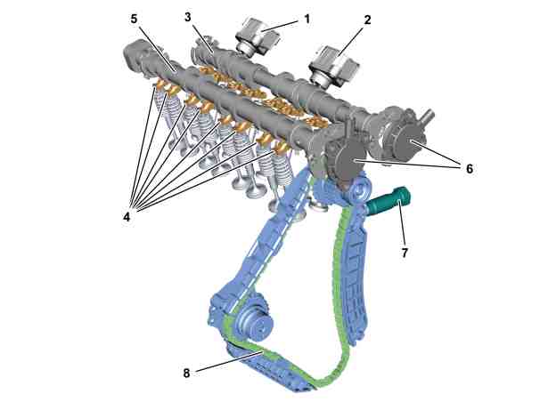
Valve timing of engine M139, component parts |
1 | Cylinder 1 and 2 exhaust CAMTRONIC actuator |
2 | Cylinder 3 and 4 exhaust CAMTRONIC actuator |
3 | Exhaust camshaft |
4 | Roller-type cam follower |
5 | Intake camshaft |
6 | Camshaft solenoid |
7 | Chain tensioner |
8 | Timing chain |
P05.00-A000-76
Combined direct and intake manifold injection
For the first time, the injection of fuel into engine M139 is performed via two-stage combined direct and intake manifold injection. The fuel injection pressure reaches up to 200 bar. As a high-pressure pump, a single-piston pump is used with a quantity control valve integrated in the pump module. The fuel is routed via a high pressure rail to the injectors, which are centrally arranged and lead into the combustion chamber. Piezo-controlled poppet valves are used as injectors.
In order to meet the requirements of engine M139 in full-load operation, intake manifold port injection with a solenoid valve is added. The electronically controlled fuel supply system operates with a pressure of 6.7 bar.
The additional injection nozzles are switched in under the following conditions in full-load operation:
Engine speed > 3,500 rpm
Engine load 60 %
Engine M139 is designed exclusively for a homogeneous combustion system. The high level of dynamics involved in the injection process with minimum opening periods results in a high pulse retention capability with an impact on the "NVH" characteristics.
An improved noise level during injection was achieved with the following parameters:
Number of injection pulses
Injector stroke
Opening gradient
Injection pressure
In the high-pressure fuel pump's flow control valve, which governs the fuel inflow into the high-pressure pump, the moving component parts have had specified reductions made to their weight.
The overall package is rounded off with enhanced decoupling of the injectors at their contact surface on the cylinder head using a so-called softer perforated disk. Their increased dampening properties help to reduce the forwarding of pulses into the structure-borne sound.
The basic requirement here is that the piezo injectors retain their exact position in the combustion chamber throughout the engine's entire service life. All in all, the rigidity of the perforated disk was reduced by around half in comparison to the predecessor engine.
Further information on the engine timing can be found in the function description "Basic function: Mixture formation" GF07.00-P-1000A.

P07.03-A005-79
Combined direct injection/intake manifold injection in engine M139, component parts |
Y76/1 | Cylinder 1 fuel injector | Y62/13 | Cylinder 1 injection valve, intake manifold | |
Y76/2 | Cylinder 2 fuel injector | Y62/14 | Cylinder 2 injection valve, intake manifold | |
Y76/3 | Cylinder 3 fuel injector | Y62/15 | Cylinder 3 injection valve, intake manifold | |
Y76/4 | Cylinder 4 fuel injector | Y62/16 | Cylinder 4 injection valve, intake manifold |
Charged by twin-scroll exhaust gas turbocharger located at rear and boost pressure control flap actuator
A major requirement for the significant output increase compared with the predecessor engine M 133 was a complete redesign of the air-carrying components upstream of the combustion chamber.
The air filter and air inlet grille were redesigned and adapted to the newly available space in the engine compartment. During this process, requirements concerning pedestrian protection also had to be taken into consideration.
The air ducting is designed so that the flow paths have as little resistance as possible to achieve low-cost flow conditions under the existing conditions.
Apart from the gas cycle design, the charge movement also has a significant influence on a high torque over large parts of the rpm range, on low fuel consumption, and on low exhaust gas emissions. For this purpose, high turbulence is generated via a corresponding design of the cylinder head. This improves the combustion process further.
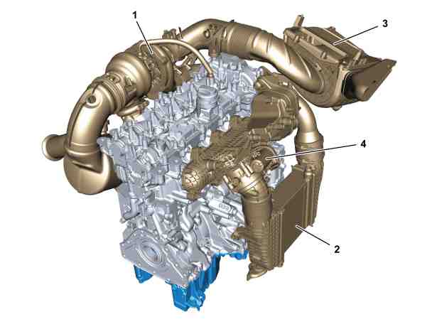
Charging of engine M139, component parts |
1 | Turbocharger |
2 | Charge air cooler |
3 | Air cleaner housing |
4 | Throttle valve actuator |
P09.00-A000-76

Sectional view of twin-scroll ATL |
1 | Turbocharger |
A | Filtered intake air |
B | Charge air |
C | Exhaust flow of cylinder 1 and 4 |
D | Exhaust flow of cylinder 2 and 3 |
P09.40-A009-76
Charging
The core component of the charging system is a twin-pipe exhaust gas turbocharger that can withstand temperatures up to 980 °C. The turbine wheel housing is fitted with integral insulation to protect surrounding components. The flow in the manifold is also separated, with cylinders 1 and 4 and cylinders 2 and 3 brought together according to their firing order.
Function sequence for boost pressure control
To enable the full potential of the exhaust gas turbocharger to develop, the boost pressure control was also completely re-engineered. The actuator, which was previously vacuum operated, is now replaced by an electrical actuator for the wastegate boost pressure control flap. As a result of its positional feedback and higher positioning rate, the boost pressure control and diagnosis are improved considerably.
The boost pressure control is realized via the boost pressure control flap actuator. It is actuated in a characteristics map- and load-dependent manner by the ME-SFI [ME] control unit for boost pressure control. To do this the ME-SFI [ME] control unit evaluates signals from the following sensors and functions of the engine management:
Pressure and temperature sensor upstream of throttle valve, boost pressure, and charge air temperature
Pressure and temperature sensor downstream of throttle valve, intake manifold pressure, and intake manifold temperature
Pressure sensor downstream of air filter, intake pressure
Accelerator pedal sensor, load request made by driver
Crankshaft Hall sensor, engine speed
Knock control, transmission overload protection, overheating protection
To reduce the boost pressure, the exhaust flow for the drive of the turbine wheel is diverted via a bypass by opening the boost pressure control flap.
The boost pressure control flap actuator actuates the boost pressure control flap, which creates the bypass, via a linkage. Part of the exhaust flow is directed through the bypass past the turbine wheel, whereby the boost pressure is regulated and the turbine speed limited. In this way the boost pressure can be adapted to the current load demand on the engine.
To monitor the current pressure and temperature conditions in the charge air duct from the exhaust gas turbocharger to the charge-air distributor, the ME-SFI [ME] control unit evaluates the signals from the pressure and temperature sensors and adjusts the boost pressure to the engine-related requirements.
Further information on the engine timing can be found in the function description "Basic charging function" GF09.00-P-9900A.
Crankcase ventilation system integrated in charge-air distributor
The crankcase in the M139 is aerated and ventilated via the charge-air distributor.

Crankcase ventilation system in engine M139, component parts |
1 | Crankcase |
2 | Charge air distributor |
3 | Purge lines |
4 | Bleed lines |
P01.40-A000-76
Belt-in-oil for oil pump operation
The M139 is supplied with oil via a mechanically driven, pressure-regulated oil pump. The drive starts at the crankshaft and then continues via a chain to the water pump and from there via a belt-in-oil to the oil pump. An electric valve integrated in the crankcase allows variable oil pressures to be adjusted depending on the characteristics maps of the engine load, engine speed, and oil temperature, in order to reduce drive output in partial-load range in particular. The exchangeable oil filter is mounted on an oil filter module or oil cooler module screwed to the oil pan. The oil cooling takes place using the oil coolant heat exchanger, which is a firmly attached part of the module.

Oil circuit of engine M139, component parts |
1 | Tandem engine oil pump |
2 | Engine oil filter |
3 | Oil pan |
4 | Toothed belt |
P18.10-A002-76
Exhaust system
The new M139 engine in the Mercedes-AMG A 45 and A 45 S models is equipped with the familiar switchable AMG Performance exhaust system with flap control. This is controlled by a characteristics map dependent on the:
AMG DYNAMIC SELECT drive program
Accelerator pedal position
Engine speed

Tailpipe trim of AMG Performance exhaust system with flap control, A 45 S |
P49.10-A035-76

Torque and power curve for engine M139 |
A | Mercedes-AMG A 45 S 4MATIC |
B | Mercedes-AMG A 45 4MATIC |
P01.00-A038-76
Technical dataM139 |
M139 | Unit | 285 kW | 310 kW |
Configuration/cylinder number | - | In line/4 | In line/4 |
Number of valves/cylinders | - | 4 | 4 |
Swept volume | cm3 | 1991 | 1991 |
Cylinder spacing | mm | 90 | 90 |
Single cylinder volume | cm3 | 498 | 498 |
Hole | mm | 83 | 83 |
Stroke | mm | 92 | 92 |
Stroke/bore | - | 1,1 | 1,1 |
Connecting rod length | mm | 138,7 | 138,7 |
Land width | mm | 7 | 7 |
Rated output | kW at 1 rpm | 285 at 6,500 rpm | 310 at 6,750 rpm |
Maximum torque | Nm at 1 rpm | 480 at 4,750 to 5,000 | 500 at 5,000 to 5250 |
Specific output | kW/l | 143,1 | 155,7 |
Compression | ε | 9,0 | 9,0 |
Emissions standard | - | Euro 6d | Euro 6d |