Operation no. of the operation texts or standard texts and flat rates | |||||
Category | Op. no. | Operation text | Time | Acc. no. | Code |
027704 | Replace coolant connection fitting on cylinder head | ||||
027705 | Replace coolant connection fitting on cylinder head (engine partly exposed) | ||||
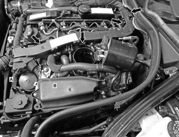
A | Cover |
B | Bracket |
Pfeile | Cable duct clip |
P20.00-2464-06

C | Holder with temperature sensor |
D | Bracket |
E | Connection fitting |
P20.00-2465-06
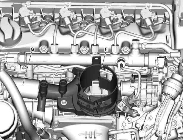
F | Connection fitting (complete) |
G | Coolant hose |
P20.00-2466-06
| Check | ||
1 | Check whether vehicle is affected by measure |
| |
From WDD2120021A181417 to WDD2120051A344152 | |||
From WDD2120051A344166 to WDD2120051A534263 | |||
From WDD2120051A534315 to WDD2122051A422293 | |||
From WDD2122051A422456 to WDD2122051A603871 | |||
If the vehicle is affected by the measure, continue with operation step 2. if the vehicle is not affected by the measure, no further action is required. | |||
| Remove/install | ||
2 | Remove exhaust gas recirculation cooler | ||
| Engine 651 | ||
3 | Unclip fuel filter with lines still connected and place to one side | Disconnect the line connection for the heating element. | |
4 | Remove cover (A) from holder (B) | Unclip the cable duct from the cylinder head cover and rail at the respective cable duct clips (Pfeile) and lift slightly. | |
5 | Unscrew holder with temperature sensor (C) and place to one side | ||
6 | Unscrew holder (D) for fuel lines and remove | ||
7 | Detach coolant hoses (E) | ||
8 | Unscrew connection fitting (F) and pull out of coolant hose (G) | Installation: The use of lubricants and liquid sealants is not permitted. | |
Installation: It is essential to attach the connection fitting (F) together with the new seal supplied. | |||
Always tighten in the following sequence: | |||
| |||
First tighten the two bolts securing the two-hole flange to the cylinder head to 10 Nm. | |||
| |||
Then tighten the three bolts for mounting on the intake manifold to 8.5 Nm. | |||
9 | Install in the reverse order | ||
10 | Fill and bleed cooling system using a vacuum in accordance with specifications. | Cooler vacuum filling device |

285 589 00 21 00
Cooler vacuum filling device
Referenced documents
- ar1420p7665cd Remove/install exhaust gas recirculation cooler
- sm2000p000601aaa Affected vehicles: Replace connection fitting
- sm2000p000601aab Affected vehicles: Replace connection fitting
- sm2000p000601aac Affected vehicles: Replace connection fitting
- sm2000p000601aad Affected vehicles: Replace connection fitting
- sm2000p000601aae Affected vehicles: Replace connection fitting