35-545 Repair to ASD ring cylinder
Preliminary jobs: |

Deep grooved ball bearing (62) | pull off, press on. Basic puller unit 001 589 36 33 00, |
Ring cylinder (60) | completely remove, install, tightening torque for Allen bolts 25 Nm. Assure that O-ring (66) is not damaged when installing ring cylinder (item 2). |
Radial shaft seal (69) | renew, see 35-540. |
Rubber cuff (63) | press off, press on. |
Ring piston (61) | press out, press in. Renew O-rings (68 and 70). Before inserting ring piston into ring cylinder coat circumference of ring piston with hydraulic oil (item 6). |
Oil types and capacity
Standard differential | Hypoid gear oil SAE 90 |
Limited slip differential with ASD (indicator plate on rear axle housing) | Special hypoid gear oil |
Capacity, center piece with ring gear dia. 210 | 1.3 liters |
Capacity, center piece with ring gear dia. 185 | 1.0 liters |
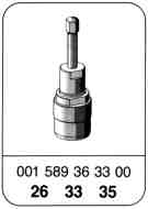
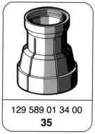

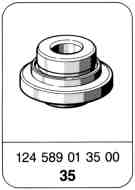
Special tools

Removal, installation
-------------------------------
1 Press deep grooved ball bearing off of connection flange with basic puller unit 001 589 36 33 00 and clamping tool 129 589 01 34 00, press on.

Installation note
Press deep grooved ball bearing (62) on so that bezel or groove (arrow) points toward shaft. Press deep grooved ball bearing on with suitable pipe (062) until it makes contact on flange.

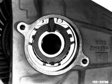
2 Screw out Allen bolts (60a) for mounting ring cylinder, screw in and remove together with ring cylinder (60).
Installation note
Assure that oil baffle plate in rear axle housing is seated correctly.

Coat circumference of O-ring on ring cylinder with oil and insert into rear axle center piece. Assure that O-ring is not damaged (arrow).
Tightening torque for Allen bolts: 25 Nm.

3 Clamp ring cylinder in vise on connection for hydraulic line.

4 Press radial shaft seal out of ring piston toward rear with punch, press in (see 35-540, arrows).
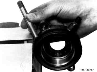
5 Press rubber cuff off of ring cylinder or ring piston at circumference with suitable punch.
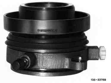
Installation note
Press rubber cuff onto ring piston with smaller diameter of installation punch 124 589 01 35 00.
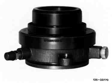
Press rubber cuff onto ring cylinder with larger diameter of installation punch 124 589 01 35 00.

6 Press ring piston out of ring cylinder, press in.
When pressing ring piston into ring cylinder assure that the groove coincides with the clamping sleeve (or bore) (dotted line).

Installation note
Renew O-rings (68 and 70) and assure that O-rings are not twisted when installing, otherwise they can be damaged when they are inserted into the ring cylinder. Coat circumference of ring piston (61) and O-rings (68 and 70) well with hydraulic oil.
60 Ring cylinder
61 Ring piston
63 Rubber cuff
65a Clamping sleeve
66 O-ring (80 x 2)
68 O-ring (72 x 3)
69 Radial shaft seal
70 O-ring (63 x 2.5)
7 Reassemble in opposite order.
Referenced documents
- bb0040p023503a FE manual transmission oil (specification 235.3)
- bb0040p023504a Synthetic transmission oils SAE 75 W/85 W (specification 235.4)
- bb0040p023504a
- ra35001070500x 0500 - Distinguishing characteristics, installation survey for rear axle center piece - Rear axle drive Model 126
- ra35001070510x 0510 - ASD design and function A. General, B. Electrical/Electronic, C. Hydraulic, D. Mechanical Model 126
- ra35001070511x 0511 - Important notes on towing, brake test and repair jobs Model 126
- ra35001070540x 0540 - Replacement of the radial sealing ring of the rear axle shaft (rear-axle center piece installed) Model 126
- ra35001070670x 0670 - Remove and install the connection flange on the rear axle shaft (rear-axle center piece installed) Model 126
- ra3500107ta02z Technical modifications: Rear axle - Drive Models 107, 126 from 09/85