35-530 Replacement of radial sealing ring on drive pinion
(rear axle center piece installed)
Operation no. of the operation texts and work units |

Rear axle oil | drain and fill up to oil fill hole (see Specifications for Service Products page 235 and 235.3). |
Rubber rings on exhaust system (120-122a) | unhook on center and rear mufflers, hook on. Support exhaust system on rear muffler (item 2). |
Exhaust guard plate (108) | remove, install, 25 Nm (item 3). |
Propeller shaft clamping nut (110b) | loosen, tighten, 30-40 Nm, |
Propeller shaft intermediate bearing (110a) | screw off, screw on, 25 Nm (item 4). |
Propeller shaft (110) | remove at joint flange (41), install, renew self-locking hex. nuts, M10 = 40 Nm, M12 = 60 Nm (items 5 and 6). |
Rear axle shafts (28) on connection flanges | remove, install and tie in place (items 7 and 8). |
Friction moment at rear axle center piece | measure and note, 100 589 02 59 00. |
12-point collar nut (40) | loosen or tighten in increments until measured friction moment is achieved (item 10), retaining wrench 116 589 10 07 00, socket wrench socket 30 mm 126 589 02 09 00, torque wrench 001 589 74 21 00. |
Joint flange (41) | remove, reinstall, pull with puller 116 589 19 33 00 if required (item 11). |
Radial shaft seal (42) | press out of rear axle housing, press in, installation tool 124 589 02 15 00. |
Thrust washer (43a) | renew if present (item 13). |
Oil level | check, add oil if required. |
Oil types and capacities
Standard differential | Hypoid gear oil SAE 90 |
Limited slip differential with ASD (indicator plate on rear axle housing) | Special hypoid gear oil |
Capacity, center piece with ring gear dia. 210 | 1.3 liters |
Capacity, center piece with ring gear dia. 185 | 1.0 liters |

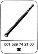


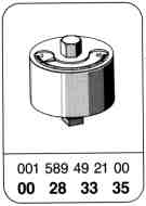
Special tools

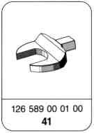

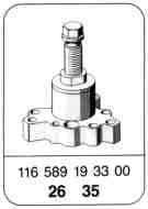
Note
The work sequence for removal and installation of the radial shaft seal is identical for models 107 and 126.

Removal, installation
-------------------------------
1 Drain oil from rear axle, refill (arrows).
Installation note
Pay attention to oil types and capacities.

2 Unhook rubber rings on center and rear mufflers, hook in and support rear muffler with suitable belt.
Arrangement, model 126

3 Remove exhaust guard plate, install.
Installation note
Tightening torque for M8 hex. nuts and bolts:
25 Nm.
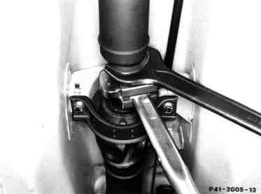
4 Loosen clamping nut, tighten and screw propeller shaft intermediate bearing off on frame floor, screw on.
Installation note
Clamping nut 30-40 Nm,
propeller shaft intermediate bearing 25 Nm.
Torque wrench 001 589 66 21 00,
open-end wrench 46 mm 126 589 00 01 00.

5 Remove propeller shaft on rear axle center piece, install.
Installation note
Renew self-locking hex. nuts.
Tightening torque M10 = 40 Nm; M12 = 60 Nm.
Note
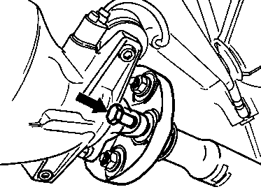
On models 126.03/04 up to approx. beginning of 10/85 the three hex. head bolts for mounting the joint plate on the joint flange must be installed from the rear toward the front for reasons of space. The bolts can only be inserted when the joint flange is located at the same height as the point on the rear axle housing marked with an arrow.

Secure propeller shaft against falling with binding wire; for this purpose use two mounting screws of exhaust guard plate (arrows).

7 Screw rear axle shafts off at connection flanges, screw on and remove with retaining bolts (28m) and washers (28n), reinstall.
Assure that the screwdriver insert is completely inserted into the serrated or Allen profile when loosening the retaining bolts - clean bolt head if required.
Installation note
Renew self-locking retaining bolts. On retaining bolts with M10 thread oil contact surface and thread. Tightening torque M10 = 70 Nm; M12 = 125-145 Nm.

8 Press rear axle shafts together and fasten to rear springs with wire, unfasten.

9 Measure and note friction moment of rear axle center piece.
Torque measuring instrument 001 589 49 21 00 (040b), socket wrench socket 30 mm 126 589 02 09 00 (040a), connector 3/4" 100 589 02 59 00 (040c).

10 Attach holding wrench (040) to joint flange and screw out 12-point collar nut with socket wrench socket (040a), screw in.
Note
Do not disengage lock on 12-point collar nut with pinch collar lock, only break loose.

Installation note
Renew 12-point collar nut (40). Carefully tighten 12-point collar nut in increments until measured or noted friction moment is reached. The tightening torque for the 12-point collar nut must be at least 180 Nm. If this minimum tightening torque is not reached, renew resilient spacer sleeve.
Knock 12-point collar nut into one of two grooves in drive pinion with punch so that there is no space between the groove and retaining tab (arrow, cutout). Holding wrench 116 589 10 07 00, socket wrench socket 30 mm 126 589 02 09 00, torque wrench 001 589 74 21 00.
Do not hit hard in axial direction.
Dimensions for punch, cutout bottom left
"a"= approx. 8 mm
"b"= approx. 4 mm

11 Pull joint flange off of drive pinion, use puller (041) if required, remove and insert. Puller 116 589 19 33 00.
Installation note
Check running surface for radial shaft seal on joint flange. If running surface is worn, renew joint flange.

12 Press radial shaft seal (42) out of rear axle housing with suitable screwdriver.

Installation note
Drive radial shaft seal (42) into rear axle housing against stop with installation punch 124 589 02 15 00 (042).

13 Always replace thrust washer (43a) for prevention of load change knocking, if present.
Assure that none of the retaining lugs (arrows) on the thrust washer are broken off when pressing out the radial shaft seal; remove lug in center piece if required.
14 Fill rear axle housing with hypoid gear oil up to height of fill opening (see Specifications for Service Products 235 and 235.3).
15 Install in opposite order.
Referenced documents
- bb0040p023500a Hypoid gear oils SAE 90, 85 W-90 (specification 235.0)
- bb0040p023503a FE manual transmission oil (specification 235.3)
- bb0040p023504a Synthetic transmission oils SAE 75 W/85 W (specification 235.4)
- bb0040p023504a
- ra35001070500x 0500 - Distinguishing characteristics, installation survey for rear axle center piece - Rear axle drive Model 126
- ra35001070510x 0510 - ASD design and function A. General, B. Electrical/Electronic, C. Hydraulic, D. Mechanical Model 126
- ra35001070511x 0511 - Important notes on towing, brake test and repair jobs Model 126
- ra3500107ta02z Technical modifications: Rear axle - Drive Models 107, 126 from 09/85