09 - 6020 Removing and installing turbocharger

1 Flame starting plug | coat with Hylomar SQ 32 M sealant. |
2 Fuel line | |
3 Electrical connection | |
4 Gasket | replace, TOP faces up. |
5 Backing plate | |
6 Bracket | |
7 Charge air manifold | |
8 Hexagon bolt | 25 Nm. |
9 Assembly hook | |
10 Washer | |
11 Hexagon bolt | |
12 Heat shield | |
13 Washer | |
14 Hexagon bolts | |
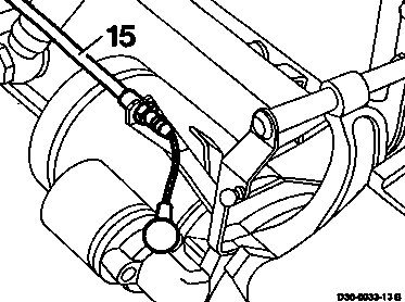
15 Bowden cable | coat ball socket with Optimol Olista Moly 2 lubricant. |
16 LDA line | |
17 Seals | replace. |
18 Banjo bolt |

19 Gasket | replace. |
20 Exhaust manifold | |
21 Washer | |
22 Hexagon bolt | 1st stage 60 Nm, 2nd stage 90° angle of rotation, coat with hot lubricating paste. |
25 Turbocharger | |
26 Locking nut | 30 Nm, replace. |
27 Exhaust pipe | |
28 Locking nut | 30 Nm, replace. |
29 Clamp | |
30 Seal | replace. |
31 Charge air line | |
32 Hose clip | |
33 Connection hose | |
34 Intake pipe | |
35 Hexagon bolt | |
36 Washer | |
37 Bracket | |
38 Crankcase breather line | |
39 Air intake hose |
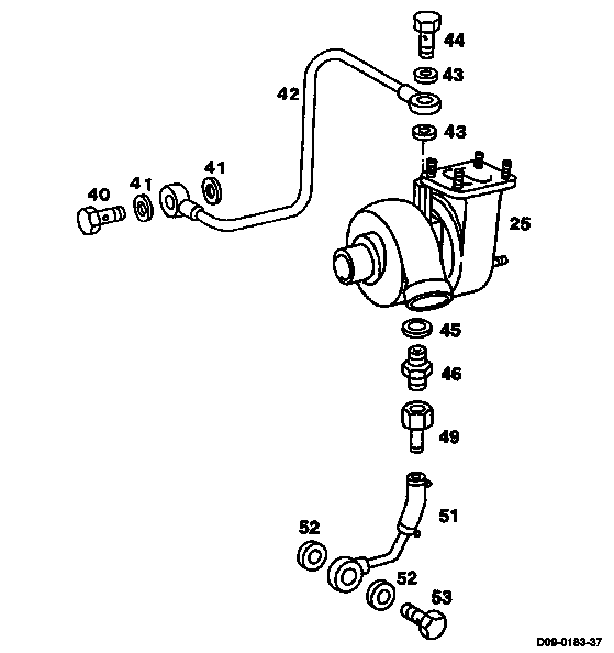
25 Turbocharger | |
40 Banjo bolt | 40 Nm. |
41 Seals | replace. |
42 Oil pressure line | |
43 Seals | replace. |
44 Banjo bolt | |
45 Seal | replace. |
46 Union | |
49 Oil return connection | |
51 Oil return hose | |
52 Seals | replace. |
53 Banjo bolt |
1 Disconnect battery.
2 Detach Bowden cable (15) at throttle control lever.

3 Slacken hexagon bolts (11) at heat shield (12) and assembly hook (9).
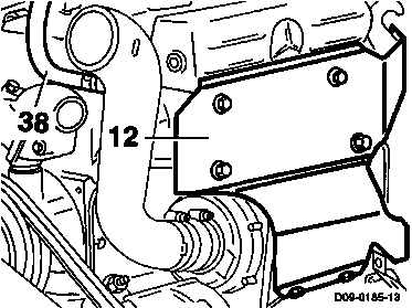
4 Take off heat shield (12).
5 Remove charge air hose.
6 Detach air intake hose and crankcase breahter line (38) at intake pipe.

7 Unscrew electrical connection (3) and fuel pipe (2) at the flame starting plug (1)
8 Unscrew flame starting plug (1) at boost air manifold.

9 Unscrew banjo bolt (18), take off LDA line (16) at charge air manifold together with seals (17).

10 Unscrew locking nut (28).
11 Take off exhaust pipe (27).
Note
Seal turbocharger openings with caps.

12 Slacken hose clip at oil return hose (51).
13 Unscrew banjo bolt (44) at oil delivery pipe (42).
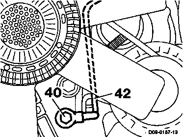
14 Unscrew banjo bolt (40) at oil pressure line at crankcase. Remove oil pressure line (42) and seals.

15 Unscrew hexagon bolts (8, 22), take off exhaust manifold (20) and charge air manifold (7) together at cylinder head. Remove gaskets.
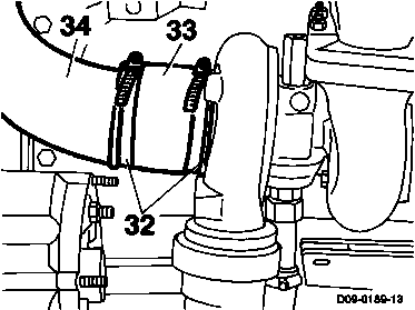
16 Slacken hose clips (32) at connection hose (33), pull off intake pipe (34) together with bracket at turbocharger connection.
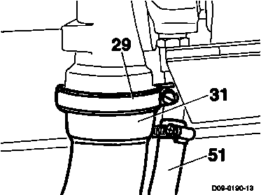
17 Slacken clip (29) at charge air line (31) and turbocharger, push onto charge air line (31).
18 Pull turbocharger out of charge air line (31) and oil return hose (51).
19 Remove exhaust manifold complete together with turbocharger and intake pipe.
Note
Seal turbocharger openings with caps.
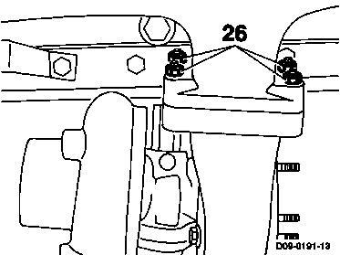
20 Unscrew locking nuts (26), detach turbocharger from exhaust manifold.
Note
Seal turbocharger openings with caps.

21 Unscrew oil return flow connection (49). Unscrew connection (46) together with seal (45) at turbocharger.
Installation
-------------------------------
Note
Before attaching the turbocharger, the intake line and flange manifold upstream of the compressor, the exhaust manifold and the exhaust pipe as well as the oil pressure line and oil return hose must be very carefully examined for foreign bodies, impurities and damage. Do not remove the caps on the openings of the turbocharger until just before installing. Before connecting the oil pressure line, fill the bearing housing with fresh engine oil through the oil inlet hole. When doing this, turn the rotating parts by hand so that the bearings are provided with a film of oil.
1 Clean sealing surfaces on turbocharger and attached parts and check for even surface.
2 Screw oil return connection (49) and new seal (45) tight, 25 Nm.
3 Assemble turbocharger and exhaust manifold and screw tight with new locking nuts (26),
30 Nm.
4 Insert new seal into charge air line, push clip (29) over charge air line (31).
5 Install exhaust manifold complete with turbocharger and intake pipe; when doing this, push turbocharger connection over charge air line (31) and introduce oil return connection into the hose (51).
Note
Also install oil pressure line.
6 Install intake pipe (34) and connection hose (33).
7 Fit new gaskets to exhaust manifold, screw exhaust manifold tight with hexagon bolts,
1st stage 60 Nm,
2nd stage 90° angle of rotation.
Note
Coat hexagon bolts with hot lubricating paste.

8 Clean sealing surfaces, attach charge air manifold (7) with new gaskets (4), TOP facing up.
9 Tighten hexagon bolts (8), 25 Nm.
10 Screw on oil pressure line (42) with banjo bolt and new seals, 25 Nm.
11 Screw hose clips tight to oil return hose (51).
12 Screw oil pressure line (42) tight with banjo bolt (40) and new seals, 40 Nm.
13 Attach exhaust pipe (27) and screw tight with new locking nuts (28), 30 Nm.
14 Attach crankcase ventilation line (38) and air intake hose.
15 Attach charge air hose.
16 Attach heat shield (12) for the turbocharger.
17 Screw heat shield (12) and assembly hook (9) tight with the hexagon bolts (11).
18 Attach Bowden cable (15) to throttle control lever.
Note
- Grease ball socket Optimol Olista Moly 2.
- Adjust throttle control (30-1010).
19 Attach LDA line (16) with new seals (17) to charge air manifold. Screw banjo bolt (18) tight.
20 Screw flame starting plug (1) into charge air manifold.
Note
Seal flame starting plug (1) with Hylomar
SQ 32 M.
21 Tighten electrical connection (3) and fuel pipe (2) at the flame starting plug (1).
22 Connect battery.
23 Adjust engine oil to correct level.
24 Start engine, check for normal operation and leaks.
Note
The starter must not be operated for more than 20 seconds otherwise it will overheat and may be damaged. If no oil pressure is indicated after the first attempt at starting the engine, wait about 1 minute in each case before the next attempt, or start engine and run at idling speed. Keep a check on engine oil pressure gauge. A constant oil pressure must be indicated after about
10 seconds.
Referenced documents
- ra0913d000300x 0003 - Sectional view Engine 364 LA (Euro2) Engine Model 354
- ra0913d000400x 0004 - Special tools Engine 364 LA (Euro2) Engine Model 354
- ra0913d000500x 0005 - Technical data Engine 364 LA (Euro2) Engine Model 354
- ra3013d101000x 1010 - Adjusting accelerator control Engine 364 LA (Euro2) Model 354