09-5010 Testing flame starting system
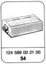
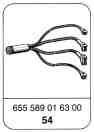
Special tools
Shop-made tool

Connection cable from flame starting system cable harness (plug connection unplugged at control unit) to test cable part no.655 589 01 63 00.
1 8-pin connector housing to flame system cable harness
2 4-pin connector housing to flame system cable harness
3 14-pin connector housing to test cable
part no. 655 589 01 63 00

Connection diagram for cables
1 8-pin connector housing to flame system cable harness
2 4-pin connector housing to flame system cable harness
3 14-pin connector housing to test cable part no.
655 589 01 63 00
Designation | Qty. | Part number |
Connector housing | 1 | 655 545 04 28 |
Connector housing | 1 | 001 545 82 28 |
Connector housing | 1 | 002 545 12 28 |
Contact springs | 12 | 003 545 18 26 |
Connector sleeves | 12 | 002 545 06 28 |
Cable 0.75 mm2, 20 cm long | 12 |
Testing
1 Test the flame system in accordance with the operating instructions "Starting engine".
2 If the indicator lamp of the flame system never lights up for more than 35 seconds during preglow or lights up constantly when the engine is running, perform test of electrical system.
3 If the electrical system is in proper order and the charge air manifold downstream of the flame system is not warm (temperature check), replace flame glow plug.
4 If the flame glow plug has been replaced and the charge air manifold does not become warm (temperature check), perform measurement of fuel pressure.
Starting engine
1 Insert key in steering lock and turn to Drive position.
Notes
- The flame system indicator lamp must come on.
- At a coolant temperature above 15°, the indicator lamp goes out after about 2 seconds (function check).
- At a coolant temperature below 15 °, the flame system is switched on automatically. The indicator lamp goes out after about 20 seconds .
2 After the flame system indicator lamp has gone out, start engine with the key at the steering lock without depressing the accelerator.
Notes
- If the engine does not start after about 5 seconds, slowly depress accelerator pedal.
- If necessary, interrupt starting operation after not more than 20 seconds and repeat after about 10 seconds.
- Before again starting engine, turn key back as far as the stop. Turn key into Drive position again and after the flame system indicator lamp has gone out, start engine immediately with the accelerator pedal depressed.
- After three attempts at starting, wait a short time before the next attempt.
- After starting the engine, release the key.
The flame system switches off automatically if
- the engine is not started within 30 seconds after the flame system indicator lamp going out
- the engine is started so long as the indicator lamp is illuminated
- the charge indicator lamp does not go out when the engine is running
- the coolant temperature with the engine running reaches 25° C.
Notes
- A fault in the flame system is indicated if the flame system indicator lamp does not go out or if it comes on when the engine is running.
- The flame system does not operate if the engine is started before the flame system indicator lamp has gone out or if the charge indicator lamp comes on when the engine is running.
Test of electrical system
Test step | Test scope | Contact box / Test connection | Operation / Requirement | Specification | Possible causes if deviation from specification |
1 | Voltage supply tml 30 | 28 25 | Ignition: OFF | 21 - 29 volts | Fuse F19 tml 30 faulty or no ground connection at 8/2 |
1a | Voltage supply tml 30 | 28 22 | Ignition: OFF | 21 - 29 volts | |
2 | Voltage supply tml 15 | 30 24 | Ignition: ON | 21 - 29 volts | Fuse F6 tml 15 faulty or no ground connection at 8/3 |
3 | Alternator terminal D+ | 28 32 | Ignition: ON Start engine | 21 - 29 volts | Fuse A4 F1 5A faulty, alternator D + faulty |
4 | Starter control | 28 27 | Ignition: ON Operate starter | 21 - 29 volts | Terminal 50 actuation faulty |
5 | Flame system indicator lamp | 28 33 | Ignition: ON | Indicator lamp comes on | Indicator lamp faulty |
6 | Solenoid valve | 28 29 | Ignition: OFF | approx. 20 W to 35 W at 20 °C | Solenoid valve faulty <8 W or >35 W |
7 | Glow plug | 28 23 | Ignition: OFF | approx. 0,8 W 0,2 W at 20 °C | Glow plug faulty <0,1 W faulty >5,0 W faulty |
8 | Glow plug | 28 21 | Ignition: OFF | approx. 0,8 W 0,2 W at 20 °C | Glow plug faulty <0,1 W faulty >5,0 W faulty |
9 | Temperature switch | 28 31 | Ignition: OFF | approx.2470 W at>23 °C 3 °C and approx. 470 W at<15 4 °C | Temperature switch faulty |

Wiring diagram
1 Control unit
3 Indicator lamp
4 Temperature switch
5 Solenoid valve
6 Glow plug
Referenced documents
- ra00005010002x 0002 - General: Engine model designations Engines OM 441-443 LA, EURO I
- ra00005010004x 0004 - General: Special tools Engines OM 441-443 LA, EURO I
- ra00005010005x 0005 - General: Technical data Engines OM 441-443 LA, EURO I
- ra00005010010x 0010 - General: Tightening torques Engines OM 441-443 LA, EURO I
- ra00005010901x 0901 - Repair of tapped holes using Heli-Coil inserts Engines OM 441-443 LA, EURO I