07.3-105 Testing on/off ratio
Preceding work: | Operation No. of operation texts and work units or standard texts and flat rates: |

P07-0677-61
Air conditioning or automatic climate |
|
Selector lever | in position "P". |
Testers | connect. |
Extraction device (014) | position at exhaust tail pipe. |
Throttle control | check for ease of movement and condition. |
Ignition point | test (see table). |
Engine oil temperature | approx. 80 °C. |
Idle speed | test (see table). |
Lambda control | test (see table). |
Smooth engine running | check by switching on all ancillary components. |
Idle speed, lambda control
Engine | Model year | Idle speed | Idle speed | Lambda control |
102.961 (2.3) | 1983/1984 | 72050 | 25-31% | 2.1-4.8 volts 1) |
102.983 | 1986-1989 | 90050 | 35-45% | 5010% |
102.985 | 1985/1986 | 72050 | 25-31% | 2.1-4.8 volts 1) |
102.985 | 1987/1988 2) | 75050 | 36-50% | 5010% |
102.985 | 1991 2) | 700-800 | 58050mA 3) | 5010% |
1) Adjust. Detach oxygen sensor coupling. Take reading of control value (volts). Readout must not fluctuate. Plug together oxygen sensor coupling - readout fluctuates. Test value must not vary more than 0.8 volts from control value.
2) California 1988 and as of 1991 with fault memory: "CHECK ENGINE" warning lamp must not light up. First of all switch over KE control unit (N3) to on/off ratio output.
3) Current measurement at idle speed air valve with multimeter (wait at least 28 seconds after starting, heating speed).
TSZ ignition point
Engine | Model year | Type of fuel | Distributor Bosch No. | Setting 1) | Test value |
102.961 (2.3) | 1983/1984 | unleaded | 0 237 002 094 | 5 | 19-25 |
102.961 | 1985/1986 | 0 237 002 098 | 22-26 | ||
1) If normal-compression engines are operated with fuel of less than 98 RON (min. 88 MON) or low-compression engines with fuel of less than 92 RON (min. 82 MON), the ignition point should be retarded and adapted to the octane number of the fuel used. The rule of thumb for this adjustment is: retard ignition point by 1 - 2° CS per 1 RON. The ignition point must not be retarded more than 6° CS.
This results in reduced engine power output and increased fuel consumption. In addition, the engine must not be operated at full load. Full ignition advance should be re-set as soon as fuel of the specified octane number is available.
EZL ignition point
Engine | Model year | EZL ignition | Resistance trimming plug | Engine speed in 1/min | Ignition point | Ignition point |
102.983 | 1986/1987 | 004 545 57 32 | Reference resistor 750 W | 4000 | 18-22 1) | 29-33 1) |
Idling | 14-18 | 14-18 | ||||
102.985 | 1987/1988 | 005 545 30 32 | 3200 | 25-29 | 39-43 | |
Idling | 8-12 | 8-12 | ||||
102.985 | 1989 | 007 545 47 32 2)3) | 3200 | 23-27 | 39-43 | |
Idling | 8-12 | 8-12 | ||||
102.985 | as of 1991 | 010 545 59 32 010 545 60 32 | Reference | 3200 | 22-26 4) | 39-43 4) |
Idling | 8-12 | 8-12 | ||||
1) Intake air temperature sensor connector unplugged.
2) These ignition control units may also be installed in vehicles prior to 1988. In this case, the ignition point values alter as shown in the table.
3) Test ignition point at 80 °C coolant temperature by unplugging the temperature sensor connector B11/2 and feeding in 320 W with resistance decade between green/black cable and engine ground.
4) For testing, unplug the intake air temperature sensor and coolant temperature sensor connectors. Test ignition point at 80 °C coolant temperature by feeding in 320 W with resistance decade between contact 1 at 4-pin connector and engine ground.
Note
Ignition control unit with ignition map for manual and automatic transmission (activated by different EZL resistance trimming plugs), boiling protection correction (max. 5° CS), intake air correction (max. 7° CS) and safety retarded adjustment (6° CS) in the event of open circuit to EZL resistance trimming plug.


Special tools
Lambda-
Regelungs-
tester
Commercially available testers
Engine tester (rpm, dwell angle, ignition angle) | e. g. Bosch, MOT 001.03 |
Twin socket | e. g. Hermann, ECD 53 |

Shop-made tool
Drift for inserting steel anti-tamper lock
P07-0586-11

Note
The adjustment device (2) for the fuel/air mixture setting is secured with a steel anti-tamper lock (1) to prevent any unauthorized alteration of the setting.
This anti-tamper lock is factory-inserted with a special tool after the fuel/air mixture is set and must not be removed in the workshops.
The fuel/air mixture setting may only be corrected when replacing a component of the injection system (e. g. fuel distributor) or when performing engine repairs.
In such cases, the adjustment device (2) must be replaced.
1 Steel anti-tamper lock
2 Adjustment device
3 Hexagon head
4 Mixture regulating screw
P07-0585-13
The lambda control must not be tested when the engine is very hot, e. g. immediately after driving sharply or after measuring engine output on the dynamometer.
1 Switch off air conditioning or automatic climate control. Move selector lever into position "P".
2 Connect testers:
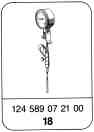
Oil remote thermometer (018) 124 589 07 21 00
Lambda control tester (012)
Twin socket (031)
Engine tester (026)
Trigger clamp (011)
3 Position extraction device (014) at exhaust pipe.
4 Check throttle control for ease of movement and condition.
5 Test ignition point (see table).
6 Run engine to warm up oil to 80 °C.
7 Test idle speed (see table).
Note
If idle speed varies, test electronic idle speed control (07.3-112).
8 Test lambda control (see table).
Note
The readout must fluctuate during the measurement. If a constant readout is indicated, there is a fault in the lambda control, e. g. oxygen sensor faulty. See "Testing electrical components of KE injection system" (07.3-121) for trouble diagnosis table.
a) Measuring on/off ratio with lambda control tester at diagnosis socket.
Engine 102.983
Engine 102.985 as of 1987
Test value: 5010%
Press 100 % IR button on Bosch lambda control tester.
California 1988 and as of 1991 Engine 102.985 with fault memory:
The KE control unit must be switched over to on/off ratio output with the pulse counter or with the non-locking switch (California only) at the diagnosis test coupling X92 or X11/4 (see also 07.3-121, Section F).
California versions:
Press switch (2, arrow) at test coupling (X92 or X11/4) for between 2 and 4 seconds.
LED (4) flashes once (no fault stored in system).
Again press switch (2) for between 2 and 4 seconds, KE control unit is switched over to on/off ratio output. LED shows steady light.
Requirement:
"CHECK ENGINE" warning lamp does not light up.

P07-0744-33

b) Voltage measurement with multimeter or lambda control tester (12 volt position) at contact 3 of diagnosis socket to ground.
Engine 102.961 (2.3) 1983/1984
Engine 102.985 up to 1986
Test value: 2.1-4.8 volts
P07-2317-13

Switch off all ancillary components.
Detach oxygen sensor signal plug connection
(G3/2x2). Take reading of control value (e. g.
3.3 volts). Readout must not fluctuate.
Plug together oxygen sensor signal plug
connection (G3/2x2) - readout fluctuates. Test
value must vary not more than 0.8 volts from
control value. Variation >0.8 volts, set control
value.
P07-2135-13A

9 Adjust lambda control.
Should it be necessary to set the on/off ratio after performing engine repairs or replacing a part of the KE injection system, procede as follows:
Take off air cleaner.
Strike shear-off screws (arrow) in the middle with a chisel and drill approx. 6 - 8 mm deep with a 2.5 mm twist drill.
P07-2375-13
Do not drill through screws as the metal chips may cause engine damage. Thoroughly remove metal chips with a cloth.
Unscrew shear-off screws with left-hand drill.
Install new repair kit, Part No. 102 070 01 74. Tighten screws until head shears off.
Fit on air cleaner.
Start engine.

Push the screwdriver (1) through the recess in the top of the air cleaner onto the adjusting device (2).
Press the adjusting device down with the screwdriver against the spring force, turn it slightly until the hexagon head (3) engages in the mixture regulating screw (61).
Turning to the left = leaner - on/off ratio or
voltage rises
Turning to the right = richer - on/off ratio or
voltage drops
After each adjustment, briefly blip throttle and test lambda control; re-set if necessary.
P07-0595-15
Switch off engine.
Take off air cleaner.
Knock in steel anti-tamper lock (1) with shop-made drift at the chamfered side far enough for the surface of the anti-tamper lock to be flush with, or slightly lower than, the bottom edge of the taper of the adjusting device (2).
1 Steel anti-tamper lock
2 Adjusting device
3 Hexagon head
4 Mixture regulating screw
P07-0585-13

Note
Since January 1989 the steel anti-tamper lock (1) has been designed as a steel ball (B). Previously steel cylinder (A).
P07-0067-15
Production breakpoint: 12/88
Model | Vehicle ident end no. |
124 Station Wagon | F 096787 |
124 Sedan | A 933300 |
124 Coupé | A 934867 |
201 | F 574637 |
Install air cleaner.
Check smooth engine running by moving selector lever into Drive mode, switching on air conditioning/automatic climate control, turning power steering to full lock. The engine must continue to run smoothly. Test electronic idle speed control, if necessary (07.3-112).
Referenced documents
- ra0000102ta30x Technical modifications: Mechanical/electronic gasoline injection-system Engine 102 KE injection
- ra07031020002x 0002 - Model and component overview Engine 102 KE injection
- ra07031020004x 0004 - Vehicle features A. Basic/national versions (CH/S) KAT, B. National versions (AUS/CH/I/J/S/USA), C. Distinguishing features KAT/without KAT, engine 102.910
- ra07031020005x 0005 - Influencing parameters of the mechanical/electronic mixture adaptation A.-B. Basic version KAT/RÜF and national version (AUS/CH/J/S), C.-D. National version 1988/1991 (USA) engine 102.985 KE
- ra07031020013x 0013 - Function diagram of the KE injection system A. 102.961, B. 102.983, C. 102.96/98 KAT/RÜF, D. 102.91/96/98 KAT, E. 102.99 KAT F. 102.961/62/85, G. 102.961(AUS), H. 102.96(CH/S), I. 102.982(CH/S), J. 102.985
- ra07031020112x 0112 - Testing the electronic idle speed control Engine 102 KE
- ra07031021213x 0121.3 - Testing the electrical components C. National version (J/USA) KE II; (J) Engine 102.962 to model year 1986, (USA) Engine 102.961, 102.985 to model year 1986
- ra07031021216x 0121.6 - Testing electrical components - F. National version (AUS/J/USA) KE III; (AUS) from 1986 Eng. 102.910/962/982/985, (J) from 1987 Eng. 102.962/982/983/990 (USA) 1987/88 Eng. 102.983/985, (USA) from 1991 Eng. 102.985