07.2-156 Removing, installing carburetor (after testing)
Operation no. of operation texts and work units or standard texts and flat rates 07-6000 |

Air filter cover | remove, install. |
Ring nut (3) for crankcase ventilation | unscrew, screw on. |
Three nuts (2) for air filter mounting | unscrew, screw on, |
Air filter (1) and warm air hose (4) | remove, install. |
Electric connectors (5) | detach, plug in. |
All hoses (6) | detach, attach. |
Fuel hoses (7) | detach, attach, check for leaks. |
Ground cable | unscrew, screw on. |
Accelerator control rod (8) at throttle valve lever, Tempomat/cruise control rod at carburetor |
detach, attach. |
Three carburetor mounting bolts (10) | unscrew, screw in, |
Rubber flange (11) | examine for signs of damage, renew if necessary. |
Idle speed, idle exhaust emissions level/ |
test, adjust (07.2-100). |
Arrangement of vacuum lines
A Evacuation connection for fuel evaporation control system (brown ring).
B Connection for automatic transmission.
C Control connection for regeneration valve of fuel evaporation control system (white ring).

As of September 1989 an additional connection (D) is located above the vacuum connection (C) for the fuel evaporation control system. The vacuum for controlling the exhaust gas recirculation as well as the fuel evaporation control system is supplied parallel from both connections.
Commercially available tool
Inserts for hexagon socket Torx bolts | e. g. Hazet, |
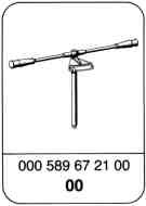
Special tool
Repair Instructions
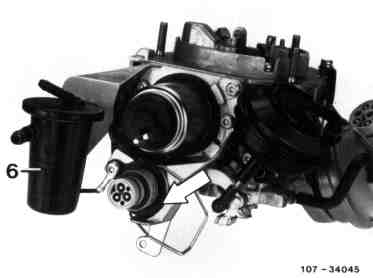
Since December 1986 a gas separator (6) is integrated in the fuel supply line of the carburetor. This separates out vapour bubbles which may cause engine running problems at high outside temperatures (e. g. hot engine does not respond immediately when moving-off particularly after short stop).
Retrofitting gas separator (07.2-176).
The fuel return runs from the gas separator along a fuel expansion hose into the return line, eliminating the return connection at the carburetor. | If a carburetor with gas separator is fitted to a car which previously had a carburetor without a gas separator, the fuel hoses should be routed as shown in the illustration. Pay attention to the lengths of the fuel hoses. |

Carburetor with gas separator (1st version from 12/86)
9 | Fuel expansion hose (approx. 300 mm) |
10 | Protective hose and check valve |
11 | Fuel hose (approx. 560 mm) |
12 | Clamp |
13 | Fuel hose |
2 | Fuel hose (approx. 40 mm installed only if gas separator has been retrofitted). |
4 | Bracket |
5 | Molded hose (approx. 200 mm) |
6 | Gas separator |
7 | Fuel hose (approx. 120 mm) |

Carburetor with gas separator (2nd version as from 09/88)
C | Fuel return to fuel tank |
119 | Gas separator |
A | Fuel feed |
B | Fuel return |

Carburetor with gas separator (3rd version as of 09/89).
The gas separator is fitted with a Y distributor (arrow). This can be retrofitted.
Referenced documents
- ra07001020001x 0001 - Model designations, installation overview, distinguishing feature KAT/RÜF Engine 102 - 2 E-E Carburetor
- ra07001020090x 0090 - Description of design and function General, Brief description, Components and arrangement, Function details Engine 102 - 2 E-E Carburetor
- ra07001020100x 0100 - Testing, adjustment of idle speed and special exhaust emission test (ASU) Engine 102 - 2 E-E Carburetor
- ra07001020176x 0176 - Retrofitting a gas seperator Engine 102 - 2 E-E Carburetor
- ra0700102pr4ax Programmed repairs: Carburetor system Engine 102 - 2 E-E Carburetor
- ra0700102ta00x Technical modifications: Carburetor system Engine 102 - 2 E-E Carburetor