05-3831 Replacing valve seat rings
Preceding work: Valves removed. Valve guides examined, replaced if necessary (05-3731). Precombustion chambers removed (01-5410). |

A | Height (cylinder head contact surface - cylinder head cover contact surface) |
B | Height (cylinder head cover contact surface - seat of valve seat ring) |
D | Valve seat ring outer diameter |
D1 | Valve seat ring inner diameter |
D2 | Basic bore diameter |
H | Height of valve seat ring |
1 | Cylinder head |
2 | Valve seat ring |
3 | Valve guide |
Data
Inlet | Exhaust | ||
Height (A min) (cylinder head contact surface - cylinder head cover contact surface) in mm | 142.5 | 142.5 | |
Height (B min) (cylinder head cover contact surface - seat of valve seat ring) in mm | 133.4 | 133.4 | |
Outer diameter of valve seat ring (D) in mm | Standard size | 40.100 40.084 | 37.100 37.084 |
Repair size | 40.600 40.584 | 37.600 37.584 | |
Inner diameter of valve seat ring (D1) in mm | 33.400 33.600 | 30.400 30.600 | |
Basic bore diameter (D2) in mm | Standard size | 40.000 40.016 | 37.000 37.016 |
Repair size | 40.500 40.516 | 37.500 37.516 | |
Overlap (U) of valve seat rings in cylinder head in mm (U=DD2) | 0.068 0.100 | 0.068 0.100 | |
Height of valve seat ring (H) in mm | Standard size | 6.955 7.045 | 6.955 7.045 |
Repair size | 7.255 7.345 | 7.255 7.345 | |
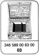
Special tool
Commercially available tools
Cylinder head clamping device | e. g. Hunger D-8000 München 70 Type Ventilknecht K 2000 Order No. 221 00 100 |
Valve seat turning tool | e. g. Hunger D-8000 München 70 Type VDS 1A Order No. 236 03 308 |
Ring seat turning tool | e. g. Hunger D-8000 München 70 Type RDS 1 Order No. 219 00 100 |
Pneumatic removal/installation device with driving drifts of 8 mm, 9 mm and 14 mm diameter | e. g. Hunger D-8000 München 70 Type PVM 1 |
Tensioning head | e. g. Hunger D-8000 München 70 Order No. 250 15 250 |
Cutting tool for recessing grooves | e. g. Hunger D-8000 München 70 Order No. 216 69 210 |
Test set for valves | e. g. Hunger D-8000 München 70 Order No. 217.93 601 |
Internal measuring micrometer (range 25-60 mm) | e. g. Mahr D-7300 Esslingen Order No. 844 |
External micrometer (range 25-60 mm) | e. g. Mahr D-7300 Esslingen Order No. 40 S |
Electrically heated water tank | e. g. Otto Dürr D-7123 Sachsenheim-Ochsenbach |

Procedure
-------------------------------
1 Measure dimension (A).
Limit:
Amin =142.5 mm.
If the measurement obtained is less than the limit, the cylinder head should be replaced.
2 Clamp cylinder head in cylinder head clamping device.
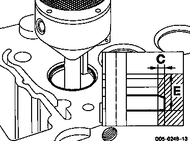
3 Turn groove in the valve seat ring so that dimension (C) is approx. 2 mm and dimension (E) approx. 6 mm.
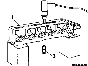
4 Take cylinder head (1) out of the cylinder head clamping device and place it onto wooden blocks.
5 Remove valve guide (3) with removal/installation device and suitable driving drift.
Drift 8 mm (inlet)
Drift 9 mm (exhaust)
Note
The valve guide must be driven out from the cylinder head contact surface side to the cylinder head cover contact surface side.
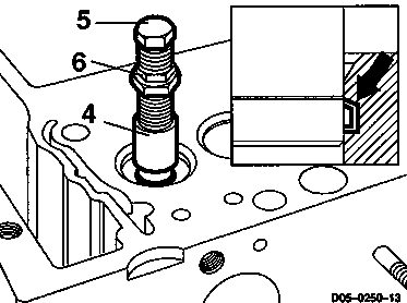
6 Insert tensioning head (4) and spread wedges (arrows) by turning the hexagon bolt (5).
Note
Screw hexagon bolt (5) tight with caution otherwise the valve seat ring in the cylinder head will be excessively tensioned.
7 Lock hexagon bolt (5) with hexagon nut (6).
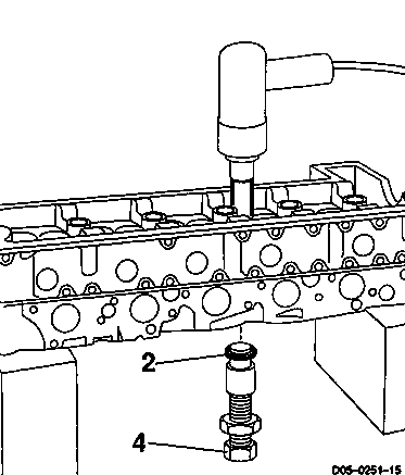
8 Turn over cylinder head.
9 Remove valve seat ring (2) and tensioning head (4) with removal/installation device and drift (14 mm).
10 Clean basic bore of valve seat ring.
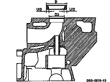
11 Measure basic bore diameter (D2) and outer diameter (D) of new valve seat ring (standard size) and note readings obtained.
12 The overlap (U) is obtained from the valve seat ring outer diameter (D) minus the basic bore diameter (D2).
Specification:
U=0.068 - 0.100 mm.
Example:
Measurement obtained (D2) =37.010 mm (exhaust).
Measurement obtained (D) =37.100 mm (exhaust).
D = 37.100 mm
- D2 = 37.010 mm
U = 0.090 mm
If the minimum overlap is not achieved, the basic bore for a valve seat ring (repair size) must be machined.
13 Clamp cylinder head in cylinder head clamping device.

14 Machining basic bore for valve seat ring (repair size):
Dimension (B min) must be maintained.
14.1 Turn basic bore.
Limits:
D2 max=40.516 mm (inlet).
D2 max=37.516 mm (exhaust).
Bmin=133.4 mm.
14.2 Measure machined basic bore and outer diameter (D) of valve seat ring (repair size) and note readings obtained.
14.3 The overlap (U) is obtained from the valve seat ring outer diameter (D) minus the basic bore diameter (D2).
Specification:
U=0.068 - 0.100 mm.
Example:
Measurement obtained (D2) =37.480 mm (exhaust).
Measurement obtained (D) =37.600 mm (exhaust).
D = 37.480 mm
- D2 = 37.600 mm
U = 0.120 mm
The basic bore diameter (D2) must be turned by 0.020 mm in order to obtain the required overlap.

15 Attach cylinder head (1) to the lifting device and heat in water bath.
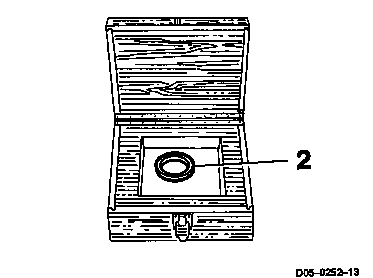
16 Supercool new valve seat ring (2) in supercooling box with liquid nitrogen.
Do not touch supercooled valve seat rings with bare fingers.
Pay attention to safety precautions.
346 589 00 63 00
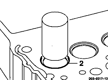
17 Drive in new valve seat ring (2) with a suitable drift (wood).
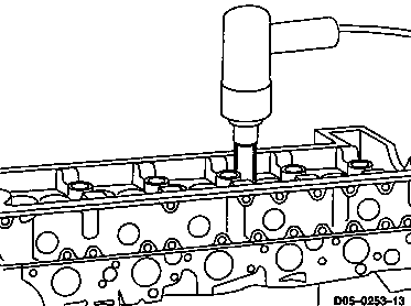
18 Install valve guide (3) with removal/installation device and suitable drift.
Drift 8 mm (inlet)
Drift 9 mm (exhaust)
Notes
The valve guide must be driven in from the cylinder head cover contact surface side to the cylinder head contact surface.
Ensure that the contact of the snap ring when installing the valve guide is indicated by a "higher" tone of the installation device.
19 Machine valve seats (05-4511).
Referenced documents
- ra0002d000200x 0002 - Installation overview Engines 601.940/941, 602.940
- ra0002d000300x 0003 - Sectional views Engines 601.940/941, 602.940
- ra0002d000400x 0004 - Special tools Engines 601.940/941, 602.940
- ra0002d000500x 0005 - Technical data Engines 601.940/941, 602.940
- ra0102d541000x 5410 - Removal and installation of precombustion chamber Engines 601.940/941, 602.940
- ra0502d000500x 05-0005 General: Technical data Engine 601.940/941, 602.940
- ra0502d373100x 3731 - Checking and replacement of valve guides Engines 601.940/941, 602.940
- ra0502d451100x 4511 - Machining valve seat Engines 601.940/941, 602.940