05-3020 Removing and installing valve springs
A. Cylinder head removed
Preceding work: Cylinder head removed (01-5800). |

1 | Valve tappet |
2 | Valve collects |
3 | Valve spring retainer |
4 | Valve spring check, replace if necessary |
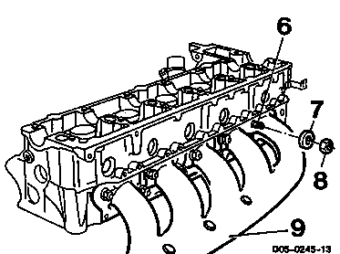
5 | Cylinder head |
6 | Stay bolt 12 Nm |
7 | Washers |
8 | Copper hexagon nuts replace, 25 Nm |
9 | Exhaust manifold |
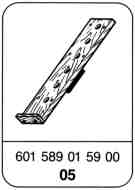


Special tools
Removing, installing
-------------------------------
1 Slacken copper hexagon nuts (8) evenly and unscrew.
Installation note
Replace copper hexagon nuts (8), 25 Nm.
2 Take off washers (7).
3 Take off exhaust manifold (9) together with gasket.
Installation notes
Examine stay bolt (6) for signs of damage; replace, if necessary, 12 Nm.
Replace gasket.

4 Screw cylinder head (5) tight to assembly board (11) with four cylinder head bolts (10).
11 601 589 01 59 00
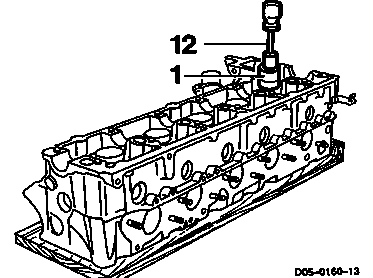
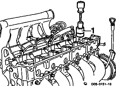
5 Pull out valve tappet (1) with magnetic lifter (12).
Installation note
Valve tappets must be installed in the same order in which they were removed. Oil valve tappets (1).
12 102 589 03 40 00

6 Place supporting bar (13) onto the cylinder head (5) and screw tight.
13 601 589 02 59 00

7 Push valve spring retainer (3) down with lever presser (14) and take out valve collets (2) with magnetic finger (15).
Note
Do not damage guide of the valve tappet.
14 601 589 02 61 00
15 116 589 06 63 00

8 Take out valve spring retainer (3) and valve spring (4).
Note
On engines OM 602 the supporting bar must be switched over once.
Installation note
Install valve spring (4) with the colour coding (arrow) facing down.
9 Examine valve spring (05-3010); replace if necessary.
10 Install in the reverse order.
B. Cylinder head installed
Preceding work: Camshaft removed (05-6292). |
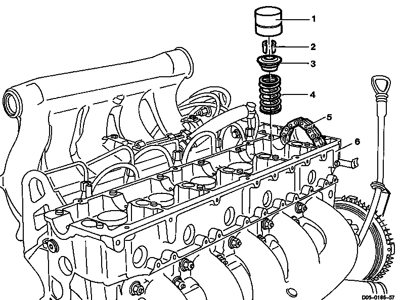
1 | Valve tappet |
2 | Valve collets |
3 | Valve spring retainer |
4 | Valve spring examine, replace if necessary |
5 | Timing chain |
6 | Cylinder head |
Remove valve springs only at the cylinders positioned at TDC.


Special tools
Procedure
-------------------------------
1 Pull out valve tappet (1).
102 589 03 40 00

2 Insert retaining wheel (7) into the timing chain (5).
3 Position piston of the relevant cylinder to TDC.
7 603 589 01 40 00

4 Screw supporting bar (8) tight above the respective cylinder.
8 667 589 02 63 00

5 Push valve spring retainer (3) down with lever pusher (9) and take out valve collets (2) with magnetic finger (10).
9 667 589 00 31 00
10 116 589 06 63 00
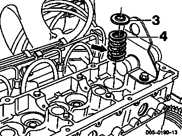
6 Take out valve spring retainer (3) and valve spring (4).
7 Examine valve spring (05-3010); replace, if necessary.
8 Insert valve spring (4) with the colour coding (arrow) facing down and insert valve spring retainer (3).
Do not damage guide of valve tappet.
9 Press valve spring retainer (3) down with lever pusher (9) and insert valve collets (2) with magnetic finger (10).
9 667 589 00 31 00
10 116 589 06 63 00
10 Position next cylinder to TDC and repeat procedure.
11 Take off supporting bar.
12 Take retaining wheel (7) out of the timing chain (5).
7 603 589 01 40 00
13 Oil valve tappets (1) and install in the reverse order in which they were removed.
102 589 03 40 00
Referenced documents
- ra0002d000200x 0002 - Installation overview Engines 601.940/941, 602.940
- ra0002d000300x 0003 - Sectional views Engines 601.940/941, 602.940
- ra0002d000400x 0004 - Special tools Engines 601.940/941, 602.940
- ra0002d000500x 0005 - Technical data Engines 601.940/941, 602.940
- ra0102d580000x 5800 - Removal and installation of cylinder head Engines 601.940/941, 602.940
- ra0502d000500x 05-0005 General: Technical data Engine 601.940/941, 602.940
- ra0502d201000x 2010 - Checking hydraulic valve clearance compensation elements Engines 601.940/941, 602.940
- ra0502d301000x 3010 - Checking valve springs Engines 601.940/941, 602.940
- ra0502d629200x 6292 - Removal and installation of camshaft Engines 601.940/941, 602.940