03-4352 Removing crankshaft, fitting new bearings and installing
Preceding work: Removing timing case (01-8205). Removing vibration damper or hub (03-1600). Removing pistons (03-7004). |

1 Crankshaft bearing cap bolts (vertical) | reusable up to shaft length of max. 156 mm, Tightening torques: 1st stage 100 Nm, 2nd stage 200 Nm, 3rd stage 300 to 330 Nm, 4th stage 90° to 100° angle of rotation. |
2 Crankshaft bearing cap bolts (side) | reusable up to shaft length of max. 86.3 mm, Tightening torques: 1st stage 80 to 90 Nm, 2nd stage 90° to 100° angle of rotation. |
3 Race | |
4 Crankshaft | guide drift 403 589 02 63 00. |
5 Straight pin | |
6 Crankshaft sprocket | |
7 Main bearing shells | |
8 Thrust bearing shells |
Data
Dimensions Crankshaft bearing Crankshaft bearing Width of thrust
journal dia. dia. when installed bearing
Standard 104.000 104.112
103.980 104.066
37.81
37.74
Undersize 0.1 103.900 104.012
103.880 103.966
Undersize 0.25 103.750 103.862
103.730 103.816
38.31
38.24
Undersize 0.5 103.500 103.612
103.480 103.566
Undersize 0.75 103.250 103.362
103.230 103.316
38.81
38.74
Undersize 1.0 103.000 103.112
102.980 103.066
Out-of-roundness of bearing journals max. 0.02
Basic bore dia. for crankshaft bearings in crankcase 111.040
110.970
Axial play of crankshaft (thrust bearings) 0.150 - 0.322
Radial play of crankshaft (thrust bearings) 0.087 - 0.153
Radial play of crankshaft (main bearings) 0.080 - 0.146
Hardness of crankshaft journals over two thirds of circumference Rockwell hardness
HRC 56



Special tools

Removal
1 Unscrew hexagon bolts (9) and take off front housing cover.

2 Mark crankshaft bearing caps and crankshaft bearings to each other in accordance with the sequence.
3 Unscrew all hexagon bolts (1 and 2) and take off bearing caps.

4 Screw in one guide drift (arrows) each at front and rear crankshaft ends and remove crankshaft.
Guide drift 403 589 02 63 00
5 Take bearing shell halves out of the crankcase and match to crankshaft bearing caps.
6 Check parts for signs of wear and damage.
Note
The bearing shells for the crankshaft are supplied ready for installation. No reworking may be performed on these parts. The thrust bearings are supplied oversized for repair purposes. The crankshaft should be re-ground according to the bearing shell width. Maintain axial play of crankshaft.

Fitting new bearings
1 Clean bearing points in crankcase and bearing cap only with chamois leather.
2 Insert bearing shell halves in the correct order into the crankcase and into the crankshaft bearing caps and oil.
Note
The locking lugs (arrow) of the bearing shells must be seated in the slots of the basic bores and crankshaft bearing caps. The oil drillings in the bearing shells and crankcase must be aligned.
3 Insert marked crankshaft bearing caps with bearing shells into the crankcase.

4 Gauge shaft length of vertical crankshaft bearing cap bolts (max. 156 mm for re-use).
5 Gauge shaft length of the side crankshaft bearing cap bolts (max. 86.3 mm for re-use).
6 Tighten vertical crankshaft bearing cap bolts (1) in the following stages.
1st stage 100 Nm
2nd stage 200 Nm
3rd stage 300 to 330 Nm
4th stage 90° to 100° angle of rotation
7 Tighten side crankshaft bearing cap bolts (2) in the following stages.
1st stage 80 to 90 Nm
2nd stage 90° to 100° angle of rotation

8 Set 100 - 160 mm dia. internal measuring instrument and dial gauge with 100 - 125 mm micrometer to the zero size of the crankshaft bearing journals.
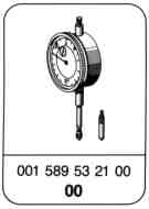
Dial gauge 001 589 53 21 00

9 Measure crankshaft bearing bore with internal measuring instrument at three points (vertical and 30° each away from separation point up and down).
Dial gauge 001 589 53 21 00
Note
The figures stated in the table must be maintained.
10 Unscrew crankshaft bearing caps again.
Fitting new bearings and installing
Note
The bearing shell halves with the dark back must be installed at the cap side as they are specially treated for high pressures.
1 Blow out oil galleries in crankcase from the oil pump side with compressed air.
2 Clean crankshaft, bearings and bearing seats with chamois leather. Clean oil galleries of crankshaft with wire brush and blow out with compressed air.

3 Test hardness of crankshaft with hardness tester.
Note
Conversion table is enclosed with the hardness tester.
Hardness tester 000 589 20 21 00
4 Insert bearing shell halves in the correct order into the crankcase and into the crankshaft bearing caps and oil.
Note
The locking lugs (arrow) of the bearing shells must be seated in the slots of the basic bores and crankshaft bearing caps. The oil drillings in the bearing shells and crankcase must be aligned.
5 Insert crankshaft with guide drifts (arrows) into the bearing shells in the crankcase.
Guide drift 403 589 02 63 00

6 Markings (arrows) on camshaft sprocket and crankshaft sprocket must be aligned.

7 Insert marked crankshaft bearing caps (arrows) with bearing shells into the crankcase.
8 Gauge shaft length of the vertical crankshaft bearing cap bolts (1) (max. 156 mm for re-use) and tighten in the following stages.
1st stage 100 Nm
2nd stage 200 Nm
3rd stage 300 to 330 Nm
4th stage 90° to 100° angle of rotation
9 Gauge shaft length of side crankshaft bearing cap bolts (2) (max. 86.3 mm for re-use) and tighten in the following stages:
1st stage 80 to 90 Nm
2nd stage 90° to 100° angle of rotation

10 Attach holder with dial gauge to crankcase and check axial play (0.150 - 0.322 mm) of crankshaft.
Holder 363 589 02 21 00
Dial gauge 001 589 53 21 00
Referenced documents
- ra00005010002x 0002 - General: Engine model designations Engines OM 441-443 LA, EURO I
- ra00005010004x 0004 - General: Special tools Engines OM 441-443 LA, EURO I
- ra00005010005x 0005 - General: Technical data Engines OM 441-443 LA, EURO I
- ra00005010010x 0010 - General: Tightening torques Engines OM 441-443 LA, EURO I
- ra00005010901x 0901 - Repair of tapped holes using Heli-Coil inserts Engines OM 441-443 LA, EURO I
- ra01005018205x 8205 - Removal and installation of the timing case Engines OM 441-443 LA, EURO I
- ra01005018810x 8810 - Removal and installation of front housing cover, replace radial seal Engines OM 441-443 LA, EURO I
- ra03005011600x 1600 - Removal and installation of the vibration damper/hub Engines OM 441-443 LA, EURO I
- ra03005017004x 7004 - Removal and installation of the pistons Engines OM 441-443 LA, EURO 1