PP07.51-P-5000DF | Pneumatic diagram (HFM-SFI) | 12.8.96 |
ENGINE 104.995 in MODEL 210.055 with CODE (498) Japanese version
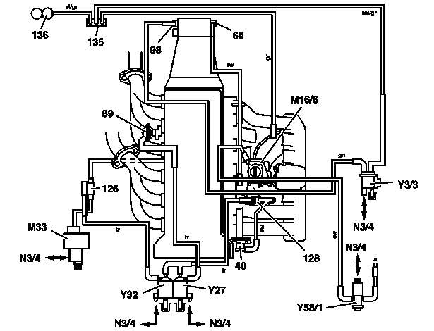
P14.30-0234-06
40 Diaphragm pressure regulator
60 Modulating pressure vacuum unit
89 EGR valve
98 Vacuum element for upshift delay
126 Air shutoff valve
128 Check valve (vacuum)
135 Check valve (vacuum supply)
136 Vacuum reservoir
M16/6 Idle speed control (ISC) actuator
M33 Electric air pump
N3/4 HFM-SFI control module
Y3/3 Upshift delay switchover valve
Y27 EGR switchover valve
Y32 Air pump switchover valve
Y58/1 Purge control valve
a Activated charcoal filter
rt red
gr grey
sw black
tr transparent
Referenced documents
- gf0751p3004d Fuel supply system HFM-SFI function
- gf1430p3012d Secondary air injection function
- gf4730p3013l Fuel evaporation control system, function