PP07.51-P-5000DE | Pneumatic diagram (HFM-SFI) | 12.8.96 |
ENGINE 104.945 in MODEL 210.053
ENGINE 104.995 in MODEL 210.055
except CODE (498) Japanese version
except CODE (491) USA version
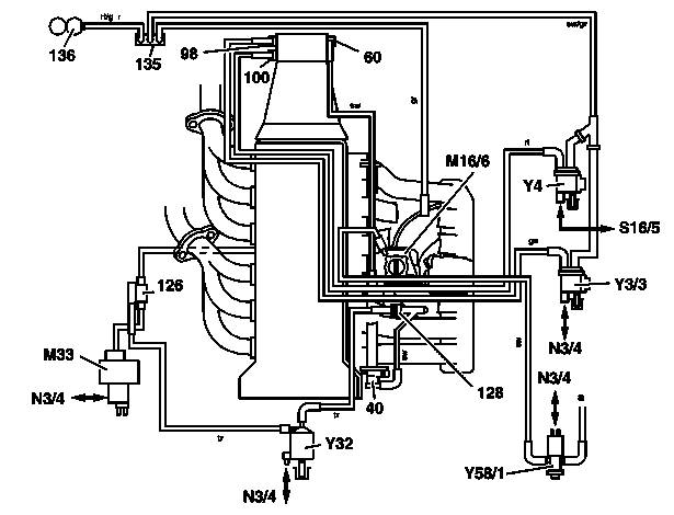
P14.00-0214-06
40 Diaphragm pressure regulator
60 Modulating pressure vacuum unit
98 Vacuum element for upshift delay
100 S and E program vacuum element
126 Air shutoff valve
128 Check valve (vacuum)
135 Check valve (vacuum supply)
136 Vacuum reservoir
M16/6 Idle speed control (ISC) actuator
M33 Electric air pump
N3/4 HFM-SFI control module
S16/5 Transmission mode switch
Y3/3 Upshift delay switchover valve
Y4 Transmission mode switchover valve
Y32 Air pump switchover valve
Y58/1 Purge control valve
a to activated charcoal filter
Referenced documents
- gf0751p3004d Fuel supply system HFM-SFI function
- gf1430p3012d Secondary air injection function
- gf4730p3013l Fuel evaporation control system, function