GF46.20-B-2001A | Single-circuit power steering when driving straightahead, function | 12.02.16 |
Steering gear 766.373, 766.375, 766.376, 766.377, 766.378, 766.379, 766.380, 766.381, 766.382, 766.383, 766.385, 766.387, 766.388, 766.394, 766.396, 766.397, 766.399
Steering gear 766.421, 766.422, 766.465, 766.469, 766.471, 766.477, 766.481, 766.482, 766.483, 766.484, 766.485, 766.486, 766.487, 766.488, 766.489, 766.495, 766.496, 766.497, 766.498, 766.499
Steering gear 766.56, 766.570, 766.580, 766.581, 766.582, 766.583, 766.584, 766.585, 766.586, 766.587

B46.25-0005-12
ZF hydraulic power steering bogearx
1 Housing
2 Piston
3 Steering rod
4 Worm screw
5 Twisting bar
6 Sector shaft
7 Pressure limiting valve
8 Refueling suction valve
9 Input slot
10 Input slot
11 Return slot
12 Return slot
13 Axial groove
14 Axial groove
15 Return groove
Low pressure in circuit
Rotating valve at neutral position
B46.20-0052-11
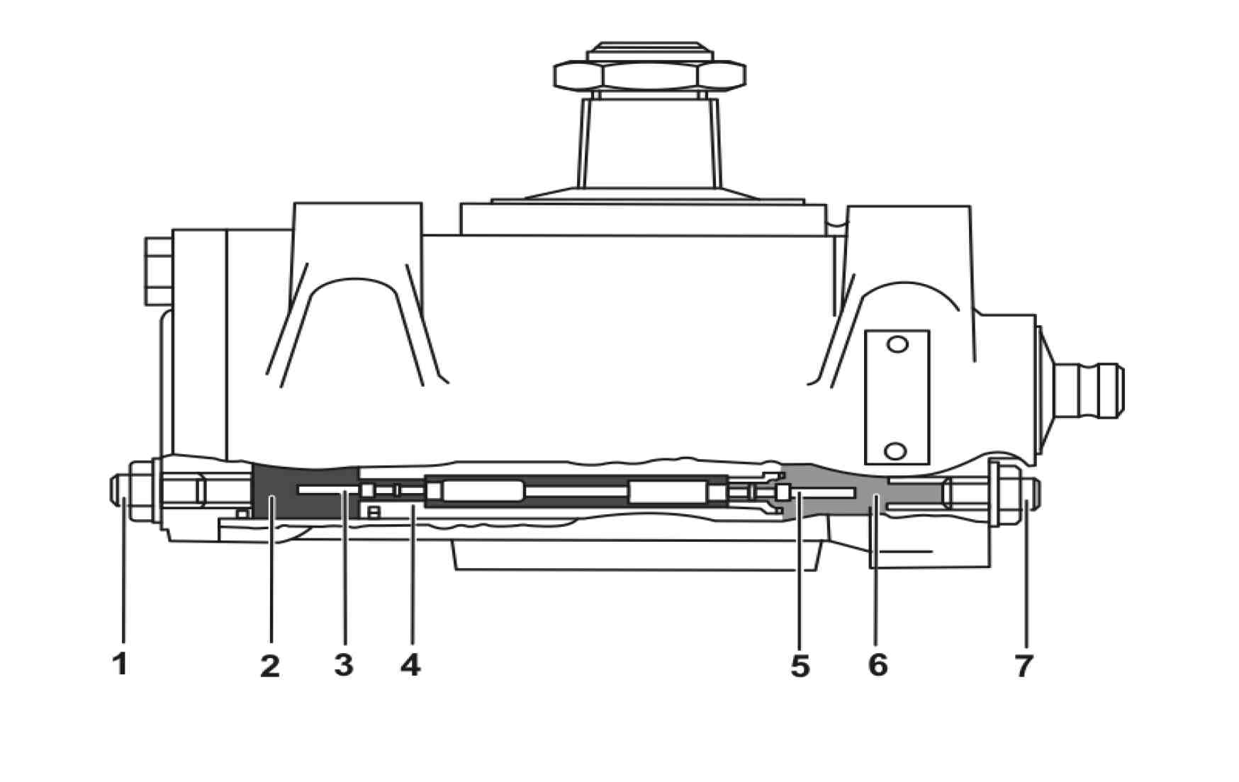
Stroke limiting valves
1 Left adjusting bolt
2 Left cylinder (Activating pin)
3 Left stroke limiting valve
4 Piston
5 Right stroke limiting valve
6 Right cylinder (Activating pin)
7 Right adjusting bolt
Operation
The rotating valve is connected to the steering rod (3) and rotates with the worm shaft (4) when turning the steering wheel
When there is no effort on the steering wheel the torsion bar (5), fastened to the rotating valve and to the worm shaft (4), maintain the same neutral position.
Oil under pressure flows at the central groove of the command bushing and is conducted to the control grooves of the inner rotating valve through three radial holes symmetrically arranged.
The position of the control grooves and the head of the worm thread is adjusted in a way that when the valve is the neutral position, the pressure oil can flow through the intake slots (9) (10) to the inside of the axial grooves in arc form(13) (14) of the worm thread head.
From there on, the oil flows freely through the radial holes to each side of the work cylinder.
While the steering valve is at the neutral position, the oil flow reaches both sides of the work cylinder, as well as flows in the direction of the three return grooves (P) of the rotating valve and returns to the canister from there.
The stroke limiting valves remain closed
Referenced documents
- gf4620b2103a Pressure reduction valve, location/task/design/function