Test and adjustment values, gap dimensions at hoods, doors and covers
Number | Designation | Model | |||
BE60.00-P-1002-01A | Gap dimension | Front door to A-pillar | Dim. "B" | mm | 8.0 (0.5) |
Front door to fender | Dim. "H" | mm | 5.0 (0.5) | ||
Front door to rear door | Dim. "I" | mm | 5.0 (0.5) | ||
Front door to roof | Dim. "C" | mm | 8.0 (0.5) | ||
Rear door to top of side section | Dim. "D" | mm | 5.0 (0.5) | ||
Rear door to side section, bottom | Dim. "J" | mm | 5.0 (0.5) | ||
Fender to A-pillar | Dim. "Q" | mm | - | ||
Front door to rear fender | Dim. "P" | mm | - | ||
See picture | |||||
BE60.00-P-1003-01A | Gap dimension | Trunk lid to rear fender, top | Dim. "F" | mm | 4.0 (0.5) |
Trunk lid to bottom of rear fender | Dim. "M" | mm | - | ||
Trunk lid to rear fender | Dim. "F" | mm | 4.0 (0.5) | ||
Trunk lid to rear lamp unit | Dim. "M" | mm | 4.4 (0.5) | ||
Trunk lid to bumper | Dim. "V" | mm | - | ||
Rear fender to rear lamp unit | Dim. "U" | mm | - | ||
See picture | |||||
BE60.00-P-1005-01A | Gap dimension | Fuel filler flap | Dim. "K" | mm | - |
Dim. "L" | mm | 4.0 (0.5) | |||
See picture | |||||
Test and adjustment values, gap dimensions at hoods, doors and covers
Number | Designation | Model | |||
BE60.00-P-1002-01A | Gap dimension | Front door to A-pillar | Dim. "B" | mm | 6.5 (0.5) |
Front door to fender | Dim. "H" | mm | 5.0 (0.5) | ||
Front door to rear door | Dim. "I" | mm | - | ||
Front door to roof | Dim. "C" | mm | 6.5 (0.5) | ||
Rear door to top of side section | Dim. "D" | mm | 5.0 (0.5) | ||
Rear door to side section, bottom | Dim. "J" | mm | 5.0 (0.5) | ||
Fender to A-pillar | Dim. "Q" | mm | - | ||
Front door to rear fender | Dim. "P" | mm | - | ||
See picture | |||||
BE60.00-P-1003-01A | Gap dimension | Trunk lid to rear fender, top | Dim. "F" | mm | 4.0 (0.5) |
Trunk lid to bottom of rear fender | Dim. "M" | mm | - | ||
Trunk lid to rear fender | Dim. "F" | mm | 4.0 (0.5) | ||
Trunk lid to rear lamp unit | Dim. "M" | mm | 4.4 (0.5) | ||
Trunk lid to bumper | Dim. "V" | mm | - | ||
Rear fender to rear lamp unit | Dim. "U" | mm | - | ||
See picture | |||||
BE60.00-P-1005-01A | Gap dimension | Fuel filler flap | Dim. "K" | mm | - |
Dim. "L" | mm | 4.0 (0.5) | |||
See picture | - | ||||
BE60.00-P-1012-01A | Gap dimension | center door to front door | Dim. "R" | mm | 5.0 (0.5) |
center door to rear door | Dim. "S" | mm | 5.0 (0.5) | ||
center door to roof | Dim. "T" | mm | 6.5 (0.5) | ||
See picture | |||||

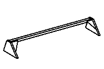

129 589 03 21 00
220 589 05 23 00
Check and welding gage
Feeler gauge
129 589 00 27 00
Bending iron

P63.50-2049-09
Shown on model 220.0/1
1 Install rear fender with clamping pliers and sheet metal screws and fasten.
For this purpose, use inspection and welding gauge.
2 Check and adjust gap dimensions:
trunk lid to upper rear fender (F),
rear door to upper side section (D) and
rear door to bottom side section (J).
Previously remove inspection and welding gauge.

P63.50-2050-09
3 Weld in rear fender with (areas A, B, C, D and arrow).

P63.50-2051-06
4 Weld in rear fender with (areas E, F, G, H, I, J and AB).

P63.50-2052-06
5 Weld in rear fender with
(areas K, N and O).
Weld at intervals in area (K) and allow to cool down in between to minimize heat distortion. Minimizes heat distortion.
6 Weld in rear fender with
(areas L and M).
7 Grind welds down flat

P63.50-2870-06
Perform steps 8.1 to 11.1 only on model 220.8.
8.1 Expose spot welds on bumper bracket (area Q).
9.1 Cut out spot welds with spot weld milling cutter or ball cutter
(area Q).
10.1 Grind rear fender down to bare metal in cross-hatched areas.
11.1 Grind bumper bracket down to bare metal around holes in cross-hatched areas.
Illustrated on model 220.8

P63.50-2882-06
Perform steps 12.1 to 16.1 only on model 220.8.
12.1 Mark intermediate section.
13.1 Cut out intermediate section
Dimensions:
a 48 mm
b 20 mm
c 7 mm
d 22 mm
e 24 mm
f 1,2 mm
g 24
h 8 mm
AA 11 mm
Illustrated on model 220.8
14.1 Drill dia. 8 mm hole (area AA).
15.1 Deburr hole on both sides.
16.1 Chamfer intermediate section

P63.50-2874-06
Perform step 17.1 and 18.1 only on model 220.8.
17.1 Fit intermediate section on bumper bracket and fasten with clamping pliers.
Center intermediate section on bumper bracket (areas of arrows and hole)
18.1 Weld in intermediate section and bumper bracket with (area R).
Illustrated on model 220.8

P63.50-2877-06
Perform steps 19.1 to 22.1 only on model 220.8.
19.1 Fit bumper bracket analog to undamaged side of vehicle.
20.1 Tack weld bumper bracket to rear fender (areas S and T).
21.1 Check position of bumper bracket by installing bumper.
22.1 Weld in bumper bracket with (areas U and V).
Illustrated on model 220.8

Perform step 23.1 only on model 220.8
23.1 Crimp rear fender (area P).
Illustrated on model 220.8
P63.50-2866-03

P63.50-2053-04
24 Crimp spot welding flange on left wheel well with crimping iron (analog to right side of vehicle).
25 Fill rear fender with body solder in cross-hatched area and smooth.
26 Clean weld joints using wire brush.