


Special tools
202 589 06 23 00
202 589 07 23 00
202 589 04 23 00
202 589 05 23 00
Template
Template
Template
Template
Parts ordering note
Part no. | Designation | Quantity |
000 986 34 42 | MB zinc dust paint |

201 589 00 51 00
Spot weld cutter
Commercially available tools
Number | Designation | |
WH58.30-Z-1002-01A | Ball cutter, dia. 12 mm | |
WH58.30-Z-1006-01A | Vario Drill WS 91 spot weld removing tool | |
WH58.30-Z-1010-02A | Sheet metal crimping shears | |
WH58.30-Z-1001-03A | Round wire brush, braided, dia. 70 mm |
Workshop equipment
WE58.40-Z-1003-03A | Angle grinder (electric/pneumatic) |
WE58.40-Z-1004-03A | Body saw (electric/pneumatic) |


P63.50-0006-01
P63.50-0005-01
1 Remove underbody protection agent with rotating wire brush.
2 Mark rear fender with marking templates in area of C-pillar and longitudinal member (dotted lines).

P63.50-0007-09
3 Expose spot welds and MIG welds and cut out
(areas A–F, arrows).


P63.50-0012-01
P63.50-0011-01
4 Cut out rear fender with body saw (arrows).
Do not damage inner side wall beneath when sawing.


P63.50-0014-01
P63.50-0013-01


P63.50-0016-01
P63.50-0015-01
5 Separate rear fender in beaded area of wheelhouse and at MIG welded joint on inside of rear center piece with disc grinder/cutter (arrows).
Do not damage inner wheelhouse panel beneath.
6 Remove damaged rear fender.
7 Pull off remaining sheet metal in area of wheelhouse with pliers.

P63.50-0017-09
8 Align welding and spot welding flanges and then grind surface down to bare metal (shaded areas).
9 Grind spot welding flanges down to bare metal on both sides.
10 . Coat insides of spot welding flanges with zinc dust paint.
P63.50-0022-01
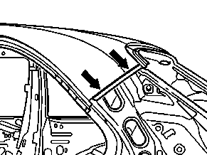
11 Crimp connection point on C-pillar (arrows).