
Shown on model 907.633 with code D03 (roof and rear-end doors, high version) except code T19 (left sliding door), left side of vehicle |
D63.10-2028-06
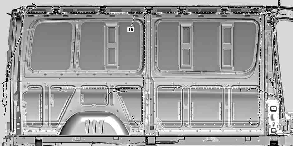
D60.00-A030-09
Shown on model 907.6 except code W16 (front left window, fixed in the side wall/sliding door) and except code W18 (front lh sliding window in the side wall/sliding door) and except code W27 (rear left fixed window) and except code W35 (rear right sliding window) and except code IR6 (wheelbase 4,325 mm, overhang 1,615 mm) and except code IR7 (wheelbase 4,325 mm, overhang 2,015 mm) |
16 | Electrical wiring harness |
Danger | Risk of death when working on component parts and systems with U >= 30 V alternating voltage (AC) or U >= 60 V direct voltage (DC) | Do not touch damaged or defective live component parts and lines or non-insulated electrical connections and lines.Model 910.6 with engine 780.703 | |
Danger | Risk of death caused by vehicle slipping or toppling off of the lifting platform. | Align vehicle between vehicle lift columns and position the four support plates at the vehicle lift support points specified by the vehicle manufacturer. | |
Topical note | Notes on carrying out repair work in the vehicle interior | ||
| Remove/install | ||
1 | Remove respective wheel well trim. |
| |
2 | Remove respective side load compartment trim. |
| |
3 | Remove tie-down rail from side wall. |
| |
4 | Remove respective rear side wall trim. |
| |
5 | Remove respective front side wall trim. |
| |
6 | Remove respective center side wall trim. |
| |
7 | Remove respective electrical wiring harness (16) in the repair area and position outside of the working area. | ||
8 | Remove respective rear wheel. | ||
9 | Remove respective protective strips. | ||
10 | Remove respective grommets behind the protective strips. | ||
11 | Install in the reverse order. |
Referenced documents
- ah6800n000101s Notes on carrying out repair work in the vehicle interior
- ar4010d1100ts Remove/install wheels
- ar6830d0016ts Remove/install wheel well trim
- ar6830d1185ts Remove/install side load compartment paneling
- ar6830d1208tsr Remove/install rear side wall trim in passenger compartment
- ar6830d1209tsr Remove/install front side wall trim in passenger compartment
- ar6830d1211tsr Remove/install center side wall trim in passenger compartment
- ar6850d8250ts Remove/install tie-down rail on sidewall
- ar8880d1040ts Remove/install moldings
- as0000z001001a Risk of death caused by vehicle slipping or toppling off of the lifting platform.
- as0000z003501a Risk of death when working on component parts and systems with U >= 30 V alternating voltage (AC) or U >= 60 V direct voltage (DC)