AR46.10-D-0200A | Remove/install clock spring contact | 17.10.11 |
MODEL 901.0 /3 /4, 902.0 /3 /4, 903.0 /3 /4, 904.0 /3 /4 with CODE (SA5) Driver airbag
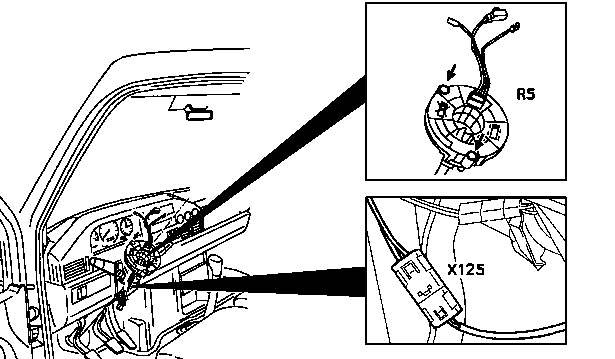
D46.10-0010-05
R5 Clock spring contact
X125 Airbag clock spring contact connector
| Remove/install | ||
Danger! | Risk of injury caused by performing testing or repair work on airbag or emergency tensioning retractor units. | Store airbag unit with deployment face up, do not subject to temperatures above 100 °C. When working on these units, disconnect the power supply. | |
1 | Remove steering wheel | ||
2 | Remove knee bolster | ||
3 | Disconnect connector for airbag clock spring contact (X125) | ||
4 | Unscrew the bolts (arrows) until the clock spring contact (R5) can be removed | Do not unscrew bolts fully. The bolts act at the same time as an anti-twist guard and assembly aid. | |
5 | Carefully take clock spring contact (R5) off steering column tube | Do not twist clock spring contact (R5) and do not disassemble. If clock spring contact is twisted (R5) see: | |
Set the clock spring contact to center position | |||
6 | Install in the reverse order |
Referenced documents
- ar4610d0100b Removing and installing steering wheel
- ar4610d020001a Set the clock spring contact to center position
- ar6810d351201a Removing knee pad
- as9100z000101a Risk of injury caused by performing testing or repair work on airbag or emergency tensioning retractor units.