AR42.10-I-0010A | Bleed brake system | 16.1.06 |
MODEL 397.243, 684.040 /081 /083 /088 /091 /093 /098 /444 /449

I42.00-0004-11
Illustrated on model 684.083
1 Cap
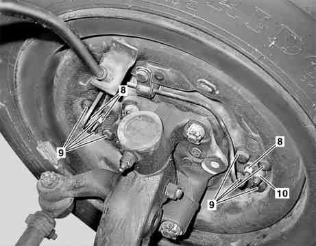
I42.00-0005-11
Illustrated on model 684.083
10 Bleed valve
Danger! | Risk of poisoning caused by swallowing brake fluid. Risk of injury caused by brake fluid coming into contact with skin and eyes. | Pour brake fluid only into suitable and appropriately marked containers. Wear protective clothing and eye protection when handling brake fluid. | |
1 | Unscrew cap (1) of reservoir | ||
| Brake fluid notes | All models | |
2 | Extract old brake fluid using a syringe | Syringe | |
| Brake fluid notes | All models | |
3 | Screw connection piece of bleeder unit on reservoir and connect pressure hose | For working pressure of bleeder unit see operator's manual. | |
Brake fluid as per Specifications for Operating Fluids. | |||
| Sheet 331.0 | ||
Bleeder unit, pneumatic | |||
Electric brake fluid change/bleeder unit | |||
| Brake fluid notes | All models | |
4 | Install drain hose of receptacle for brake fluid on vent valve (10) of wheel brake cylinder | Detach the protective cap on the vent valve (10) of the wheel brake cylinder. Start at the bleed valve (10) of the wheel brake cylinder which is furthest removed from the master brake cylinder. | |
| Brake fluid notes | All models | |
5 | Open bleed valve (10) | Keep bleed valve open (10) until new brake fluid escapes at the drain hose free of bubbles. | |
6 | Close bleed valve (10) | ||
7 | Carry out operation step 4 to 6 to each wheel brake cylinder | In each case start at the vent valve (10) of the wheel brake cylinder which is furthest removed from the master brake cylinder. | |
8 | Check brake fluid lines and all bleed valves (10) for leaks | The bleeder unit must be connected and be under operating pressure. | |
9 | Detach pressure hose from bleeder unit connector | Pay attention to manufacturer's operating instructions. | |
| Brake fluid notes | All models | |
10 | Unscrew bleeder unit connector on reservoir | ||
| Brake fluid notes | All models | |
11 | Correct fluid level in the reservoir | ||
| Brake fluid notes | All models | |
12 | Screw on cap (1). | ||
| Brake fluid notes | All models | |
13 | Carry out function test of brake system and clutch operation | If the result of the function test is not OK, repeat the bleeding process. |
Test values for hydraulic braking system
Number | Designation | Model 397.243 | Model 684.040/ | ||
BE42.50-N-1003-01C | Distance to upper edge of reservoir | mm | 10...20 | 10...20 | |
Brake system
Number | Designation | Model 397.243, 684.040/091/093/098/449 | ||
BF42.00-N-1001-01C | Brake fluid | Filling capacity | Liters | 0,8 |
Specifications for Operating Fluids | Sheet | |||
Commercially available tools
Referenced documents
- ah4250p000101a Brake fluid notes
- as4250z000101a Risk of poisoning from swallowing brake fluid. Risk of injury from skin and eye contact with brake fluid
- bb0040p033100a Brake fluids (DOT 4 plus)