AR33.10-A-0100A | Removing and installing front axle | 9.11.04 |
FRONT AXLE 733.015 in MODEL NAB372.124
front axle designation IDEM: VAMF27
FRONT AXLE 733.015 in MODEL NAB372.317
front axle designation IDEM: VAMF27

A33.10-0002-06
1 Shock absorber
2 Trailing arm
3 Transverse control arm
4 Trailing arm
5 Drag link
6 Steering idler arm
7 Trailing arm
8 Torsion bar
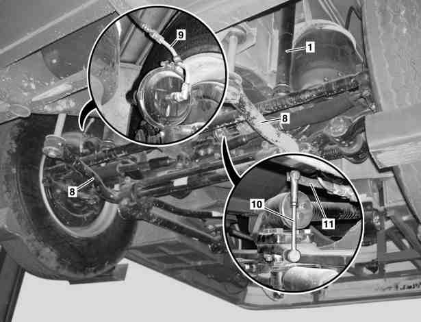
A33.10-0003-06
1 Shock absorber
8 Torsion bar
9 Compressed-air line
10 Linkage rod
11 Lever
| Remove/Install | ||
| Replace self-locking nuts and bolts. | ||
1 | Drain compressed air from compressed air system | ||
2 | Lift/jack up vehicle | ||
3 | Unscrew linkage (10) to level-control valve on the front axle | ||
4 | Slowly pull the lever (11) on the level-control valve downwards and bleed the air spring bellows | ||
5 | Unscrew brake hoses from compressed air lines (9) | Seal line openings with plugs. | |
6 | Remove drag link (5) from steering idler arm (6) | Installation: install new cotter pin. | |
7 | Remove control arm (3). | Installation: Check the split rubber rings for re-usability. | |
8 | Remove trailing arms (2, 4, 7) | Installation: Check the split rubber rings for re-usability. | |
9 | Unscrew shock absorber (1) at bottom and push upwards slightly | Installation: Check rubber shock absorbers for re-usability. | |
10 | Detach torsion bar (8) from substructure | Installation: install new cotter pin. Check rubber shock absorbers for reusability. | |
11 | Lower front axle with front wheel-engaging lifts | ||
12 | Install in the reverse order |
Trailing arms, wishbones
Number | Designation | Front axle 733.015 | |
BA33.15-N-1001-01A | Bolt of transverse control arm to front axle beam | Nm | 120 |
BA33.15-N-1002-01A | Bolt, longitudinal control arm attachment to front axle beam | Nm | 120 |

Puller
601 589 04 33 00
Referenced documents
- ar0060t1000aa Lift/jack up vehicle