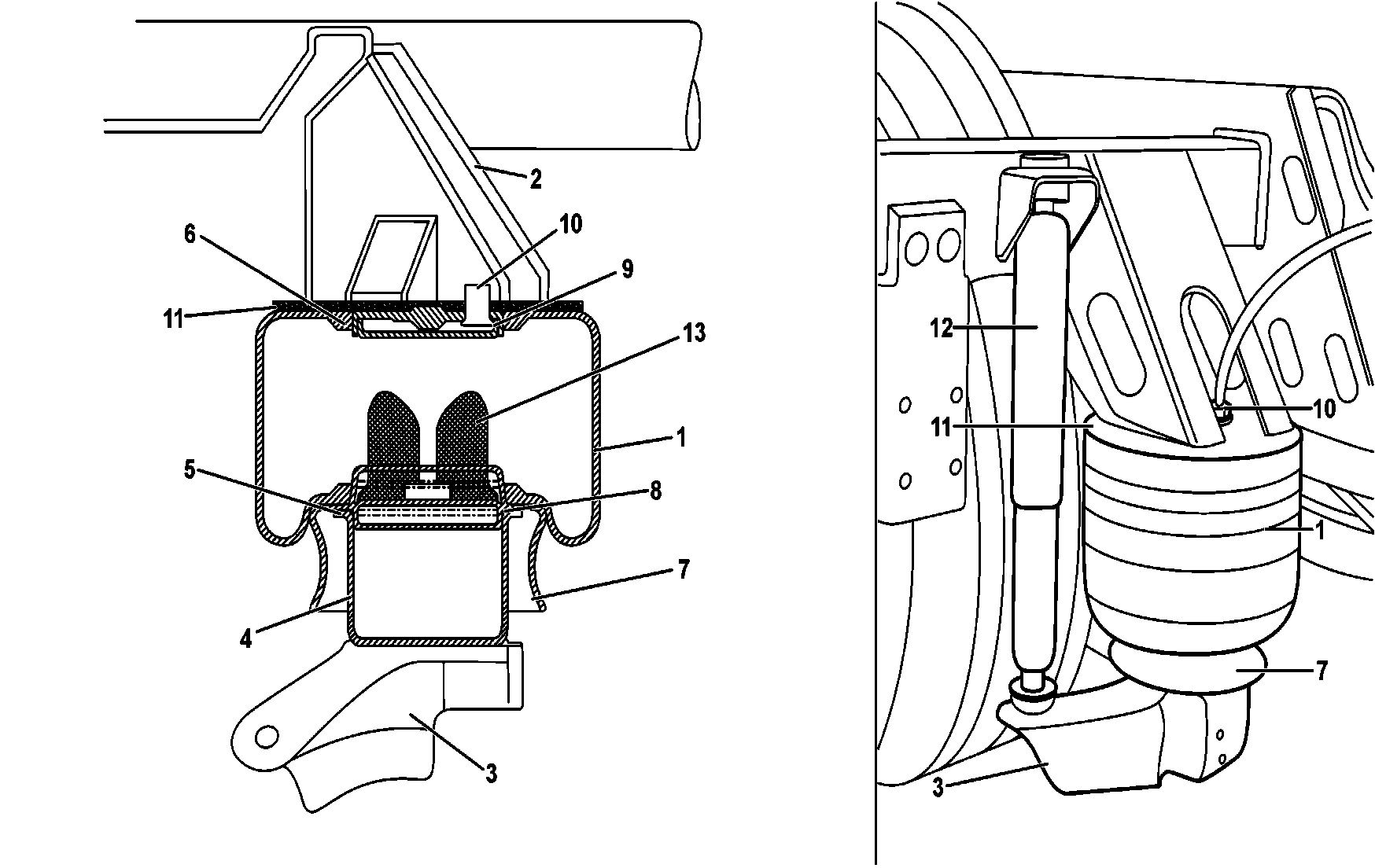
B32.22-0058-09
1 Bellows of rear pneumatic suspension
2 Vehicle structure
3 Support of rear axle pneumatic suspension
4 Bottom supporting plate integrated in the suspension support
5 Bottom sealing edge of bellows
6 Top sealing edge of bellows
7 Bellows supporting and sealing edge
8 Sealing edge on the supporting plate
9 Sealing edge on the support top ring
10 Threaded neck of the pneumatic suspension
11 Upper support
12 Rear shock absorber
13 Pressed stop on the supporting plate
| Remove | ||
Danger! | Life at risk by vehicle lowering in jobs between the wheels and the structure. Risk of injuries by crushing or pinching, in pneumatic suspension jobs | Do not work between the wheels and the rolling space or wheel wells. Carry out testing and adjustment work exclusively from the bottom of the vehicle with the assistance of a pit. Fence with safety the access to moving parts area. | |
1 | Lift the vehicle at the rear and support it on safety stands | Do not lift the vehicle by the center of the rear axle. Chock the vehicle to avid its rolling | |
2 | Remove the wheels. | ||
3 | Fully relieve the pneumatic bellows pressure | ||
4 | Detach the compressed air line at the threaded neck (10) | ||
5 | Remove the bellows (1) and the supporting plate (7) | Manually remove the bellows (1) from the sealing edge of the upper ring on the support (9) carefully and pull it out together with the supporting plate (7) in the lower part. Do not use levers or metal made tools. As a last resource, utilize a wooden lever with rounded ends. | |
6 | Separate the bellows (1) from the supporting plate (7) | ||
7 | Disassemble the stop (13) from the supporting plate (7) | Secure the assembly by the supporting plate (7) in a vise (with protection on the jaws) and utilize an appropriate lever without damaging the sealing edges. If the stop is damaged it may be cut off with a chisel. | |
| Cleaning | ||
8 | Clean all mechanical components, the supporting surfaces and the bellows | The bellows is to be dry cleaned without utilizing any cleaning liquid or solvent. Clean the sealing areas on the supporting plate (8) and on the bellows edges. | |
| Check | ||
9 | Check the sealing edges on the upper support (9) and on the supporting plate (7) on the lower part | Replace the supporting plate or the upper support if necessary. | |
10 | Check the pneumatic bellows (1) and the inside stop (13) for conditions | Replace the pneumatic bellows and the stop if they present: - Traces of leaks; - Brittleness, cuts or fissures; - Deformed inside stop; - Sealing parts corroded or deformed by the prolonged use. | |
| Installing | ||
11 | Press the stop (13) on the supporting plate (7) | Lubricate the stop with prepared and specified glycerin soap. | |
12 | Install the bellows (1) on the supporting plate (7) | Lightly lubricate all bellows mechanical and sealing parts with prepared glycerin soap. Fit the bellows (1) on the supporting plate (7) manually folding it with the palm of the hands. Do not utilize metal made tools. | |
13 | Install the bellows (1) and the supporting plate (7) on the lower cylindrical support (4) | ||
14 | Manually fit the bellows (1) on the upper support (11) fitting the sealing edge (6) on the upper ring on the support (9) | The complete fitting on the upper support (11) occurs with the pressurization of the bellows. | |
15 | Installing the wheel | ||
Danger! | Life at risk by vehicle lowering in jobs between the wheels and the structure. Risk of injuries by crushing or pinching, in pneumatic suspension jobs | Do not work between the wheels and the rolling space or wheel wells. Carry out testing and adjustment work exclusively from the bottom of the vehicle with the assistance of a pit. Fence with safety the access to moving parts area. | |
16 | Lower the vehicle. | ||
17 | Pressurize the pneumatic system | ||
18 | Check the system for possible pressure leaks | Utilize neutral glycerin soap foam. Do not utilize normal soap foam as it contains caustic soda that corrodes the materials. | |
19 | Perform a test drive | Check the behavior of the pneumatic suspension. |
Produtos para reparos
Número | Denominação | Número de pedido |
BR00.45-B-1023-06A | Slip fluid DBL 8600.10 | A 000 989 08 60 |
Referenced documents
- ar4010b1100e Remove/install wheels
- as3222b000101a Risk of death from lowering vehicle when working between wheels and body. Risk of injury from pinching or crushing when working on the air suspension.