
W28.40-1010-09
1 | Coupling flange | 7 | Compression spring | 12 | Sliding sleeve | ||
2 | Engageable front axle shift cylinder | 8 | Transfer case | 13 | Balls | ||
3 | Shift piston | 9 | Shift unit | 14 | Retaining ring | ||
4 | Shift housing | 10 | Output shaft | 15 | Ball bearing | ||
5 | Piston rod | 11 | Pressure plate | 16 | Radial shaft sealing rings | ||
6 | Shift fork |
Warning | Risk of injury. Skin or eye injuries may result when handling hot or glowing objects. | Wear protective gloves, protective clothing and safety glasses, if necessary. | |
Notes on safety-relevant components | |||
| Disassemble | ||
1 | Remove shift housing (4). | ||
2 | Detach compression spring (7). | ||
3 | Unscrew and remove locking screw. | ||
| |||
4 | Install output shaft (10) in clamping device. | Clamping device | |
5 | Detach coupling flange (1). | ||
6 | Undo screws on engageable front axle shift cylinder (2). | ||
7 | Remove engageable front axle shift cylinder (2). | To do so, apply compressed air to the compressed air connection at the engageable front axle shift cylinder (2). | |
8 | Remove shift piston (3) and piston rod (5). | ||
9 | Detach shift housing (4) from output shaft (10). | Puller | |
Adapter | |||
Hand pump | |||
Hydraulic hose (complete) | |||
Hydraulic cylinder | |||
Adapter | |||
Adapter | |||
10 | Detach shift fork (6). | ||
11 | Remove output shaft (10) from clamping device. | ||
12 | Remove 29 balls (13) from shift unit (9). | ||
13 | Detach sliding sleeve (12) from shift unit (9). | ||
14 | Detach pressure disk (11) from output shaft (10). | ||
15 | Remove retaining ring (14) from shift housing (4). | ||
16 | Remove ball bearing (15) from shift housing (4). | Use a suitable drift. | |
17 | Remove radial shaft sealing rings (16) from shift housing (4). | Removal and insertion device | |
18 | Remove pilot bushing and radial shaft sealing ring of piston rod (5) from shift housing (4). | ||
| Assemble | ||
19 | Coat new radial shaft sealing ring of piston rod (5) with lubricant and install up to contact surface using drift. | Install the new radial shaft sealing ring with the spring lock washer facing inward (oil side). | |
Synthetic grease 50 g | |||
Drift | |||
20 | Install pilot bushing of piston rod (5) up to contact surface using drift. | Drift | |
21 | Install ball bearing (15) in shift housing (4). | Use a suitable drift. | |
22 | Install retaining ring (14) in shift housing (4). | ||
23 | Heat up pressure disk (11) to approx. 80 °C and attach to output shaft (10). | The flat side of the pressure plate (11) must point toward the coupling flange (1). | |
24 | Install sliding sleeve (12) on shift unit (9). | ||
25 | Clamp shift unit (9) in a vise and shift sliding sleeve (12). | ||
26 | Install 29 balls (13) in sliding sleeve (12) with lubricant. | Synthetic grease 50 g | |
27 | Install output shaft (10) in shift unit (9). | ||
28 | Install shift fork (6) in sliding sleeve (12). | The flat side of the shift fork (6) must point toward the transfer case (8). | |
29 | Place shift housing (4) on output shaft (10). | ||
30 | Insert shift piston (3) with piston rod (5) into shift housing (4). | ||
31 | Press shift housing (4) onto output shaft (10) up to contact surface. | Hand pump | |
Hydraulic hose (complete) | |||
Hydraulic cylinder | |||
Adapter | |||
Adapter | |||
Pulling device | |||
32 | Fix shift fork (6) in place using locking screw. | ||
| |||
33 | Install radial shaft sealing rings (16) in shift housing (4). | Removal and insertion device | |
34 | Heat up coupling flange (1) to approx. 80 °C and install. | Coupling flange to front axle | |
35 | Install engageable front axle shift cylinder (2). | Shift cylinder, engageable front axle to transfer case | |
Klueber Polylub GLY 801 grease | |||
36 | Attach compression spring (7). | ||
37 | Install shift housing (4). |


715 589 15 34 00
Hydraulic cylinder
750 589 00 33 00
Adapter
715 589 12 34 00
Adapter
652 589 00 33 21
Hand pump
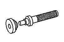


714 589 05 15 00
Drift
715 589 13 33 00
Puller
715 589 11 34 00
Adapter
750 589 00 43 00
Removal and insertion device


715 589 12 33 00
Pulling device
315 589 02 31 00
Clamping device
652 589 00 33 23
Hydraulic hose (complete)
Referenced documents
- ah0000z001901a Notes on safety-relevant components
- ar2840w1007hd Remove/install shift housing on transfer case
- ar2850w0001hc Remove/install coupling flange on transfer case
- ar2850w0001hc
- as0000z000201a Risk of injury. Skin or eye injuries may result when handling hot or glowing objects.
- wf5850w285101a Fixing screw for shift fork