AR03.30-A-8002A | Remove/install a flywheel | 15.6.09 |
ENGINE 457.939 /945 /946 /949 in MODEL NAB372.124
ENGINE 457.939 /945 in MODEL NAB372.317
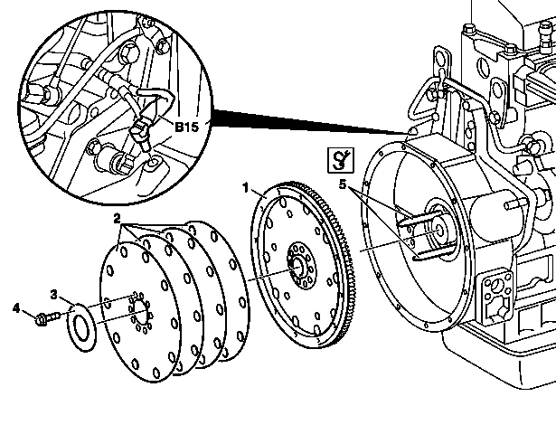
A03.30-0003-06
1 Flywheel
2 Clutch plate
3 Washer
4 Flywheel bolt
5 Alignment punch
B15 Crankshaft angle position sensor
| Remove/install | ||
1 | Open left rear maintenance flap | ||
2 | Disconnect ground cable of battery | ||
3 | Remove engine compartment flap below last row of seats | ||
4 | Remove automatic transmission | ||
5 | Remove torque converter | ||
6 | Pull crankshaft angle position sensor (B15) out of timing case | Installation: Press crankshaft angle position sensor (B15) into timing case as far as the stop. | |
7 | Attach cranking/blocking device for engine | Block cranking/blocking device by inserting the pin. Installation: The cranking/blocking device must be removed before starting engine to avoid engine damage. | |
Bolt, inspection hole cover to timing case | |||
Cranking device | |||
8 | Unscrew flywheel bolts (4) | Installation: Lightly oil flywheel bolts. | |
Bolt, flywheel to crankshaft | |||
Socket | |||
9 | Screw centering drifts (5) into two opposite threaded holes | Drift | |
10 | Remove washer (3) | ||
11 | Take off cranking/blocking device for engine | Cranking device | |
12 | Remove clutch plates (2) | Installation: All bores on the clutch plate must be congruent with each other. Center the outer bores of the clutch plates to the respective bores in the flywheel (1). | |
13 | Remove flywheel (1) over the centering drift | If flywheel is tight, screw two bolts into opposite threaded holes and pull off flywheel. | |
Installation: Grease ring gear with long-term grease. Note installation position of locking pin. | |||
Long-life grease | |||
| Checking | ||
14 | Measure flywheel bolts (4) | If the max. shank length (L) of the flywheel bolt has been exceeded: | |
Replace flywheel bolts. | |||
Flywheel bolt | |||
15 | Check flywheel flange | In case of wear or galling, drive race onto flywheel: | |
Remove/install race on flywheel | |||
16 | Inspect ring gear for wear | If worn: | |
Replace ring gear of flywheel | |||
17 | Install in the reverse order |
Test and adjustment values for a flywheel
Number | Designation | Engine | |||
BE03.30-N-1004-03E | Flywheel bolt | M161.5 | Shank length | mm | 75 |
Timing case
Number | Designation | Engine 457.9 | |
BA01.60-N-1001-01H | Bolt connecting inspection hole cover to timing case | Nm | 25 |
Flywheel, driven plate, vibration damper, starter ring gear
Number | Designation | Engine | ||
BA03.30-N-1002-01M | Bolt, flywheel to crankshaft | Stage 1 | Nm | 200 |
Stage 2 | ° | 90 | ||


422 589 02 09 00
Drift
Wrench socket
Cranking device
407 589 00 63 00
403 589 02 63 00
Repair materials
Number | Designation | Order number |
BR00.45-Z-1001-06A | Long-life grease | A 000 989 63 51 11 |
Referenced documents
- ar0330a160003a Attach/detach cranking/blocking device for engine
- ar0330a8312a Replace ring gear on flywheel
- ar0330a8350a Remove/install race on flywheel