
I62.30-0001-11
A Lower crossmember
B Upper crossmember
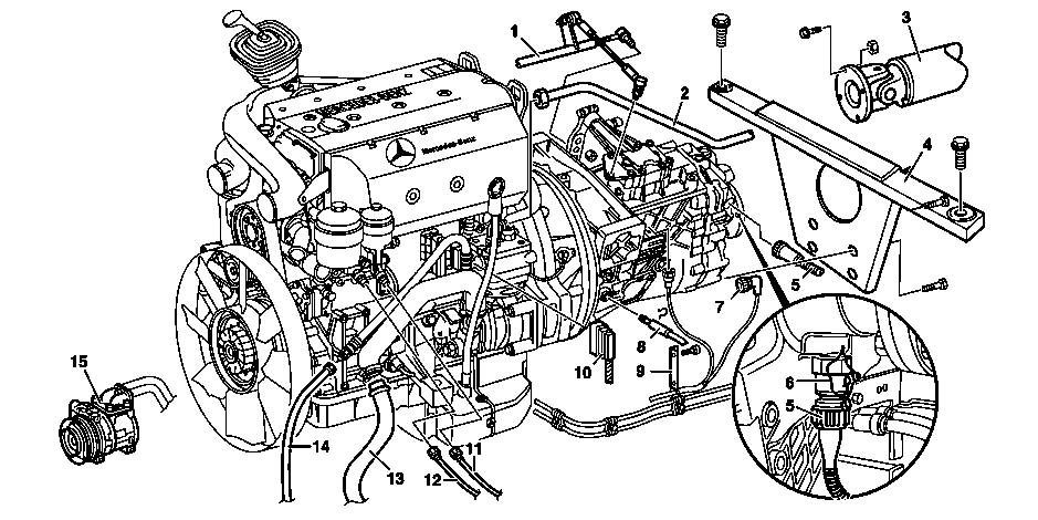
I01.10-0016-09
1 Gearshift linkage
2 Compressed-air line (to compressor)
3 Propeller shaft
4 Support arm
5 Connector (to speed sensor)
6 Tamper-proof seal
11 Fuel feed line
12 Fuel return line
13 Steering oil suction line
14 Steering oil pressure line
15 Refrigerant compressor
7 Connector plug (to neutral position switch)
8 Remove clutch line
9 Holder (with electrical wiring harness and hydraulic lines)
10 Connector plug (to MR/PLD control unit)
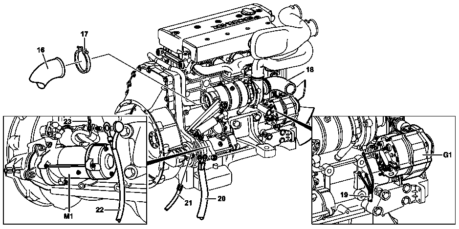
I01.10-0017-09
16 Exhaust pipe
17 Hose clamp
18 Air intake hose
19 Electrical wiring harness (to alternator)
G1 Alternator
M1 Starter
20 Ground line
21 Compressed air line (to engine brake cylinder)
22 Electrical line (to starter)
23 Electrical line (to starter)

I01.10-0021-06
32 Assembly device (shop-made)
| Remove/install | ||
Installation | Replace self-locking nuts and bolts. | ||
Danger! | Risk of accident caused by vehicle starting off by itself when engine is running. Risk of injury caused by contusions and burns during starting procedure or when working near the engine as it is running | Secure vehicle to prevent it from moving by itself. | |
Danger! | Risk of injury to skin and eyes caused by scalding from contact with hot coolant spray. Risk of poisoning caused by swallowing coolant. | Do not open cooling system unless coolant temperature is below 90°C. Open cap slowly and release the pressure. Do not pour coolant into beverage containers. Wear protective gloves, protective clothing and safety glasses. | |
Danger! | Danger of injury to eyes caused by steering oil emerging at high pressure. Danger of poisoning caused by swallowing steering oil | Unscrew end limit screws by a maximum of | |
Danger! | Risk of explosion caused by fuel igniting, risk of poisoning caused by inhaling and swallowing fuel and risk of injury to eyes and skin caused by contact with fuel | No fire, sparks, open flames or smoking. Wear protective clothing when handling fuel. | |
1 | Drain coolant | ||
| Replace coolant | ||
| Notes on coolant | ||
Danger! | Risk of explosion caused by escaping oxyhydrogen gas. Risk of injury caused by caustic burns to eyes, skin and mucous membranes from battery electrolyte (contains diluted sulfuric acid) or metal spatter due to short circuit. Risk of burn injuries caused by short circuit. Risk of poisoning caused by swallowing battery electrolyte (contains diluted sulfuric acid) or absorption of lead over the skin or orifices | No fire, sparks, open flames or smoking. Wear acid-resistant gloves and clothing and safety glasses with side guards. Do not place any conductive objects on the battery and avoid any short circuit from battery positive to ground. Only fill liquid battery electrolyte (diluted sulfuric acid) into suitable and appropriately marked containers. | |
2 | Disconnecting the battery | ||
| Notes on battery | ||
3 | Remove front bumper | ||
4 | Remove front flap | ||
5 | Remove lower crossmember (A) | ||
6 | Remove upper crossmember (B) | ||
7 | Remove charge air pipe | From charge air cooler to charge air manifold. | |
From turbocharger to charge air cooler | |||
8 | Remove radiator | ||
9 | Disconnect compressed-air line (21) from engine brake cylinder | ||
10 | Detach exhaust pipe (16) from engine brake valve connection | Installation: Clean sealing surfaces. | |
11 | Detach exhaust pipe (16) from transmission and fasten to frame | ||
12 | Disconnect air intake hose (18) from air filter housing | ||
13 | Disconnect electrical lines (22, 23) at starter (M1) | ||
14 | Disconnect electric wiring harness (19) at alternator (G1) and at bracket | Installation: Observe colored marks for electrical lines and the connecting points on the alternator (G1). | |
15 | Disconnect ground cable (20) and electrical wiring harness to timing case | ||
16 | Release connector plug (10) on MR/PLD control unit and detach | ||
17 | Remove compressed air line (2) from fitting on compressor | Inspect compressed-air line (2) for carbon deposits. In case of carbonization: | |
Check all compressed air lines between compressor, compressed air drier and 4-circuit protection valve for carbonization. Replace parts showing carbon deposits. | |||
18 | Unscrew fuel feed line (11) on fuel filter | Place match marks on fuel feed line (11) and connecting parts on fuel filter . Collect escaping fuel. | |
19 | Unscrew fuel return line (12) on fuel filter | Place match marks on fuel return line (12) and connecting parts on fuel filter . Collect escaping fuel. | |
20 | Remove poly-V belt | Only on models fitted with air conditioning | |
21 | Detach refrigerant compressor (15) at engine | Only on models fitted with air conditioning Do not remove refrigerant lines on refrigerant compressor (15). | |
22 | Remove steering oil suction line (13) from steering oil suction line to power steering pump | Collect escaping steering oil. | |
23 | Remove steering oil pressure line (14) from steering oil pressure line to power steering pump | Collect escaping steering oil. | |
Danger! | Risk of poisoning caused by swallowing brake fluid. Risk of injury caused by brake fluid coming into contact with skin and eyes | Only pour brake fluid into suitable and appropriately marked containers. Wear protective clothing and eye protection when handling brake fluid. | |
24 | Remove locking element and pull out clutch line | Collect escaping brake fluid. | |
Installation: Bleed clutch operation. | |||
| Brake fluid notes | ||
25 | Unscrew connector plug (7) on neutral position switch | ||
26 | Unscrew connector plug (5) on speed sensor | Installation: Replace lead seal (6). | |
27 | Unscrew connector plug on reverse gear switch | ||
28 | Detach bracket (9) from transmission | Do not remove electrical wiring harness and hydraulic lines from | |
29 | Remove gearshift linkage (1) on transmission | Do not alter settings on the | |
30 | Remove propeller shaft (3) to output flange | Secure propeller shaft (3) by attaching to the frame against falling down. | |
31 | Secure engine with assembly device (32) and secure a lifting truck against dropping | ||
| Device for remove/install of engine | ||
32 | Remove supporting arm (4) from transmission | | |
33 | Remove supporting arm (4) from transmission mount | | |
Check transmission bearings for wear. Replace if necessary: | |||
Detach/attach transmission mount to transmission carrier. | |||
| |||
34 | Remove left engine support and right engine support | ||
35 | Pull engine together with transmission forwards | ||
36 | Install in the reverse order | ||
37 | Reach in all transponder keys | Only perform for installation of a reconditioned engine with a new MR/PLD control unit. | |
38 | Inspect engine oil level, adjust to correct level if necessary. | ||
| Specified engine oils (service) - overview | Sheet 223.2 | |
39 | Start engine and check oil pressure indicator for idle speed | Oil pressure must be indicated after a few seconds. Do not rev up engine as long as no oil pressure is indicated. | |
40 | Stop engine and check engine oil level after a waiting time of at least 5 minutes; correct if necessary | The waiting time must be maintained. | |
| Specified engine oils (service) - overview | Sheet 223.2 | |
41 | Bleed steering system |
Check values for engine oil pressure
Number | Designation | Engine | ||
BE18.00-N-1001-01C | Engine oil pressure at | Idling speed | bar | 0.5 |
maximum speed | bar | 2.5 | ||
Complete manual transmission
Referenced documents
- ah2000n208001a Notes on coolant
- ah4250p000101a Brake fluid notes
- ah5410p000101a Notes on battery
- ah5410p000101a
- ap2000i2080b Replace coolant
- ar0941i1311b Remove/install charge air pipe
- ar0941i1311c Remove/install charge air pipe
- ar1322i1202b Remove/install poly-V belt
- ar2020i3865b Remove/install radiator
- ar2210i1200c Remove/install engine support
- ar2520i0070b Bleed clutch operating system
- ar4110i0050b Remove/install propeller shaft
- ar4625i3300b Bleed steering system
- ar8057i0010a Teach in transponder key
- as0000z000501a Risk of accident from vehicle starting off by itself when engine running. Risk of injury (bruises and burns) resulting from working on the engine while it is being started or when it is running.
- as2000z000101a Risk of injury to skin and eyes suffering scalding from contact with hot coolantspray. Risk of poisoning from swallowing coolant.
- as4250z000101a Risk of poisoning from swallowing brake fluid. Risk of injury from skin and eye contact with brake fluid
- as4600z000101a Danger of injury to eyes caused by steering oil emerging at high pressure. Danger of poisoning caused by swallowing steering oil
- as4700z000101a Risk of explosion caused by fuel igniting, risk of poisoning caused by inhaling and swallowing fuel as well as risk of injury to eyes and skin caused by contactwith fuel.
- as5410z000101a Risk of fire/risk of explosion due to short circuit and escaping oxyhydrogen gas. Risk of (burn) injury caused by caustic burns to eyes, skin and mucous membranes from battery electrolyte/mist, short circuit and arcing. Risk of
- bb0040p022302a Specified engine oils for Cars, Vans (service) - Overview
- wf5850i011003b Device for engine removal and installation