AR01.00-P-3000GF | Lower, raise engine with front axle carrier | 4.4.06 |
ENGINE 166.940 /960 /990 /995 in MODEL 168

P01.10-2141-09
1 Front axle carrier
2 Torx screw
3 Strut
4 Torx screw
5 Steering shaft
6 Steering coupling
11 Rubber base
12 Retaining clips
13 Vacuum line
Y58/1 Purge control valve
7 Thrust piece
8 Torx screw
9 Collar nut
10 Front axle carrier removal device
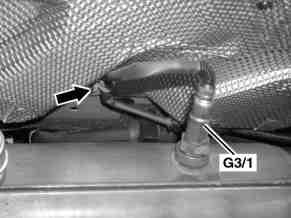

P14.10-2025-01
G3/1 O2 sensor downstream of TWC
Steering coupling with nut holder
5 Steering shaft
6 Steering coupling
7 Thrust piece
8 Torx screw
16 Nut holder
P46.10-2196-01
| Remove/install | ||
1 | Disconnect battery ground cable | ||
2 | Detach vacuum line (13) of purge system at purge switchover valve (Y58/1) | ||
3 | Remove retaining clamps (12) at the radiator | ||
4 | Detach air intake scoop and air intake duct from front end crossmember | ||
5 | Remove washer fluid reservoir | On models fitted with windshield washer fluid heater | |
Drain coolant and detach coolant hoses to windshield washer fluid reservoir | |||
6 | Disconnect electric cables of power steering pump at terminal point of left frame longitudinal member | Expose electric cables, replace clips attaching cables below terminal point. | |
7 | Detach steering coupling (6) at steering shaft (5), take off thrust piece (7) | Installation: Replace self-locking collar nut (9) or nut bracket (16). On RHS models the steering coupling is separated directly at the rack-and-pinion steering and can only be installed in one position. | |
Bolt, steering coupling to steering shaft | |||
8 | Remove complete exhaust system | Only disconnect the catalytic convertor flange connection at the exhaust system. Inspect condition of rivet nut of flange connection (bolted flange connection), if necessary | |
Replace rivet nut of flange connection | |||
Bolt of exhaust system to catalytic converter | |||
9.1 | Release cable of O2 sensor downstream of TWC (G3/1) from the retaining clip (arrow) at underfloor and expose | On engines with 2-sensor control. | |
10 | Detach alternator bracket and starter wiring harness at oil pan | ||
11 | Prepare front axle carrier removal fixture (10) | Risk of tipping during later lowering - observe adapter assignment. From model refinement package 03/2001 or VIN "WDB1680311J568590" Adapter adaptation required. | |
Additionally from VIN "WDB1680311J568590" | |||
12 | Align front axle carrier removal fixture (10) at front axle carrier (1) and put in place evenly | Risk of tipping during later lowering. | |
Additionally from VIN "WDB1680311J568590" | |||
13 | Take off strut (3) on left and right at front axle carrier (1) and at underfloor | Bolt, strut to front axle carrier and body | |
14 | Take off wheelhousing liners on left and right at underfloor and fold down | To gain access to the rear Torx bolts (2). | |
15 | Unscrew Torx screws (2) | Installation: First fit all Torx screws (2), then tighten. | |
Bolt of front axle carrier to body | |||
16 | Carefully lower front axle carrier (1) with engine | On vehicles with air conditioning, the bracket for the A/C line on the right rear front axle carrier (1) must also be detached. Lower a maximum of 80 mm. Be careful of coolant/AC hoses and electrical lines. | |
Installation: Guides (arrows) on the front-axle carrier (1) must be inserted into the holes in the longitudinal member. Pay attention to guides at radiator. Be careful of coolant/AC hoses and electrical lines. | |||
17 | Install in the reverse order |
Front axle carrier
Number | Designation | Model 168 | ||
BA33.10-P-1001-01B | Bolt, front-axle carrier to body | M 12 | Nm | 120 |
BA33.10-P-1003-01B | Strut screw to front-axle carrier | M 10 | Nm | 60 |
Steering shaft
Exhaust system
Number | Designation | Engine 166.940/ | |
BA49.10-P-1001-01D | Bolt of exhaust system to catalytic converter | Nm | 25 |
Workshop equipment
WE58.40-Z-1014-11A | Integral carrier removal device |
Referenced documents
- ar1410p409501gf Removing, installing rivet nuts
- ar2000p1142gf Drain/pour in coolant
- ar4910p7000gf Removing and installing exhaust system complete
- ar5410p0003a Disconnect/connect battery's ground cable