Model | 207.4## 1# up to 5/31/13 |
up to model year 2014 | |
with code 512 (COMAND APS with DVD changer) | |
except code 460 (Canada version) | |
except code 494 (US version) | |
except code 498 (Japanese version) | |
Model | 207.4## 1# up to 5/31/13 |
up to model year 2014 | |
with code 527 (COMAND APS with single DVD drive (with navigation)) | |
except code 460 (Canada version) | |
except code 494 (US version) | |
except code 498 (Japanese version) |


220 589 04 99 00
New passenger car wiring harness repair kit
000 589 13 99 00
Wiring harness repair kit, basic

Connection scheme |
1 | COMAND wiring harness |
2 | Backup camera wiring harness |
4 | Trunk lid wiring harness |
A40/3 | COMAND control unit |
B84/3 | Backup camera |
B84/3x1 | Backup camera electrical connector |
E4/1e3 | Right backup lamp |
N10/2 | Rear SAM control unit with fuse and relay module |
N66/10 | Backup camera voltage supply module |
W7 | Right wheelhouse trunk ground point |
X169 | Backup camera electrical connector |
br | Brown line |
gr/ge | Gray/yellow line |
rt/bl | Red/blue line |
P54.65-4285-06

Routing diagram |
1 | COMAND wiring harness |
2 | Backup camera wiring harness |
3 | Potential distributor |
4 | Trunk lid wiring harness |
A40/3 | COMAND control unit |
B84/3 | Backup camera |
B84/3x1 | Backup camera electrical connector |
E4/1e3 | Right backup lamp |
N10/2 | Rear SAM control unit with fuse and relay module |
N66/10 | Backup camera voltage supply module |
W7 | Right wheelhouse trunk ground point |
X169 | Backup camera electrical connector |
br | Brown line |
gr/ge | Gray/yellow line |
rt/bl | Red/blue line |
P54.65-4284-06

1 | Route electrical line of reversing camera (B84/3) through specified opening into interior of trunk lid and clip reversing camera (B84/3) into place. |
2 | Detach protective foil (5) from reversing camera (B84/3). |
P54.65-4287-12
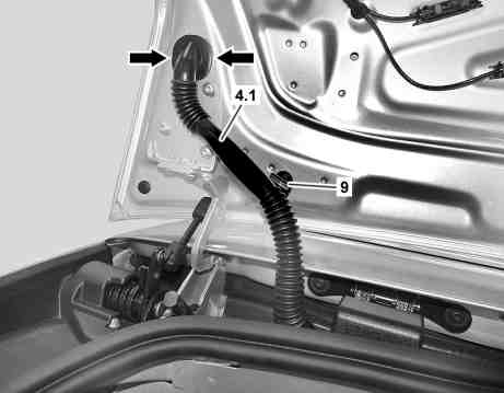
3 | Release grommet for cable duct (4.1) from trunk lid (arrows) and remove from trunk lid. |
4 | Release cable duct (4.1) from holder (9) and remove upwards out of holder (9). |
P54.65-4288-11

5 | Release catch hook (4.3) on grommet (4.2) of cable duct (4.1) and remove trunk lid wiring harness (4). |
The trunk lid wiring harness (4) is replaced by a trunk lid wiring harness (4) from the scope of supply. |
P54.65-4289-06

6 | Clip in cable duct (4.1) for new trunk lid wiring harness (4) and install new trunk lid wiring harness (4). |
Use a pull-through device. |
7 | Route trunk lid wiring harness (4) along existing lines to the reversing camera in trunk lid and fix in place using cable ties. |
8 | Make electrical connector for reversing camera (B84/3x1). |
To do so, connect the black 4-pin coupling of the trunk lid wiring harness (4) and the black 4-pin reversing camera connector. |
9 | Pull foam material (16) over the reversing camera electrical connector (B84/3x1). |
P54.65-4290-11

10 | Route trunk lid wiring harness (4) along existing lines to the installation location of reversing camera electrical connection (X169) and fix in place using cable ties. |
11 | Route reversing camera wiring harness (2) along existing lines to reversing camera power supply module (N66/10) and fasten in place using cable ties. |
12 | Make electrical connector for reversing camera (X169). |
To do so, connect the black 4-pin coupling of the trunk lid wiring harness (4) and the black 4-pin reversing camera wiring harness connector (2). |
13 | Pull foam material over the reversing camera electrical connector (X169). |
P54.65-4291-11

14 | Connect black 4-pin coupling (2.1) for reversing camera wiring harness on the power supply module wiring harness (N66/10). |
P54.65-4316-01

15 | Fit retaining clamp (7) of trunk lid wiring harness (4) onto body flange. |
16 | Preservation agent Apply preservation agent to body flange in area of retaining clamp (7). |
P54.65-4292-11
17 | Connect white 6-pin connector (1.1) of COMAND electrical wiring harness to reversing camera power supply module (N66/10). |
P54.65-4316-01

18 | Route gray/yellow line (GY/YE) along existing lines to lower grommet of cable duct (8). |
19 | Release grommet for cable duct (8) from trunk lid (arrows) and remove from trunk lid. |
P54.65-4293-11

20 | Route gray/yellow line (GY/YE) using a pull-through device through the cable duct (8) into the inside of the trunk lid. |
Spray lubricant into cable duct (8). |
21 | Clip grommet of cable duct (8) into trunk lid. |
22 | Connect gray/yellow line (GY/YE) of COMAND wiring harness to gray/yellow line (GY/YE) of right backup lamp (E4/1e3) using potential distributor (3). |
The potential distributor (3) is available in the Basic wiring harness repair kit or the Supplement wiring harness repair kit for passenger cars. |
23 | Wrap felt tape round potential distributor (3). |
24 | Fasten gray/yellow line ((GY/YE)) of right backup lamp (E4/1e3) and gray/yellow line (GY/YE) of COMAND wiring harness in place using cable ties. |
P54.65-4295-11

25 | Route brown line (BN) from reversing camera power supply module (N66/10) along given lines up to the right ground point in the trunk wheel arch (W7) and fasten in place using cable ties. |
26 | Connect brown line (BN) to right wheel arch ground point in trunk (W7) Connecting. |
27 | Strap down excess length of brown line (BN). |
P54.65-4296-11

28 | Route red/blue line (RD/BU) from reversing camera power supply module (N66/10) along given lines up to rear SAM control unit with fuse and relay module (N10/2) and fasten in place using cable ties. |
29 | Strap down excess length of red/blue line (rt/bl). |
P54.65-4297-11

30 | Detach green fuse folder (11) from rear SAM control unit with fuse and relay module (N10/2). |
Only if the rear SAM control unit with fuse and relay module (N10/2) is equipped with a green fuse holder (11). |
P54.65-4298-11

31 | Connect red/blue (RD/BU) line with the line (14) in contact cavity 4 of the green fuse holder for the vehicle wiring harness using a potential distributor (13). |
Only if the rear SAM control unit with fuse and relay module was equipped with a green fuse holder and contact cavity 4 of the green fuse holder is engaged. |
The potential distributor (13) is available in the Basic wiring harness repair kit or the Supplement wiring harness repair kit for passenger cars. |
P54.65-4299-01
32 | Open lock on green fuse holder (11). |
Only if the rear SAM control unit with fuse and relay module (N10/2) was equipped with a green fuse holder (11) and contact cavity 4 of green fuse holder (11) is not used. |
33 | Fit a suitable STP contact to the red/blue line (RD/BU). |
Only if the rear SAM control unit with fuse and relay module (N10/2) was equipped with a green fuse holder (11) and contact cavity 4 of green fuse holder (11) is not used. |
The STP contact is available in the Basic wiring harness repair kit or the Supplement wiring harness repair kit for passenger cars. |
34 | Install red/blue line (RD/BU) into contact cavity 4 of green fuse holder (11). |
Only if the rear SAM control unit with fuse and relay module (N10/2) was equipped with a green fuse holder (11) and contact cavity 4 of green fuse holder (11) is not used. |
P54.65-4298-11
35 | Install red/blue line (RD/BU) into contact cavity 4 of green fuse holder (11) included in package contents. |
Only if the rear SAM control unit with fuse and relay module (N10/2) is not equipped with a green fuse holder (11). |
36 | Insert a 7.5 A fuse into contact cavity 4 of green fuse holder (11). |
If required. |
37 | Fit green fuse holder (11) into slot with green markings on rear SAM control unit with fuse and relay module (N10/2). |
P54.65-4298-11

38 | Route COMAND wiring harness (1) from reversing camera power supply module (N66/10) over the left C-pillar into the existing line ducts and along the existing wiring harnesses to the B-pillar and fasten in place using cable ties. |
P54.65-4300-11

39 | Route COMAND wiring harness (1) from B-pillar via the A-pillar into the existing cable ducts and along the existing wiring harnesses to the COMAND controller unit (A40/3) and fasten in place using cable ties. |
P54.65-4301-11

40 | Fit green 2-pin connector (15) of COMAND wiring harness (1) to green slot of COMAND controller unit (A40/3). |
Only if the green slot of COMAND controller unit (A40/3) is not used. |
41 | Release lock of green 2-pin connector support (15) for COMAND wiring harness (1) and remove the support. |
Only if the green slot of COMAND controller unit (A40/3) is used. |
42 | Remove green 2-pin connector (15) of vehicle wiring harness from COMAND controller unit (A40/3). |
Only if the green slot of COMAND controller unit (A40/3) is used. |
43 | Release lock of green, 2-pin connector support (15) on vehicle wiring harness. |
Only if the green slot of COMAND controller unit (A40/3) was used. |
P54.65-4302-12
44 | Insert COMAND wiring harness (1) into green, 2-pin connector support (15) on vehicle wiring harness and lock. |
Only if the green slot of COMAND controller unit (A40/3) was used. |
45 | Fit green, 2-pin connector (15) onto green slot of COMAND controller unit (A40/3). |
Only if the green slot of COMAND controller unit (A40/3) was used. |