GF14.30-P-2020V | Umschaltventil Luftpumpe Bauteilbeschreibung | 13.3.08 |
MOTOR 272.920 im TYP 203 bis Modell-J. 08 /AEJ 07
MOTOR 272.922 im TYP 211
MOTOR 272.940 im TYP 203 bis Modell-J. 08 /AEJ 07
MOTOR 272.941 im TYP 203 bis Modell-J. 08 /AEJ 07
MOTOR 272.942 im TYP 171 bis Modell-J. 08 /AEJ 07
MOTOR 272.943 im TYP 211, 219
MOTOR 272.944 im TYP 211
MOTOR 272.945 im TYP 251 bis Modell-J. 08 /AEJ 07
MOTOR 272.946 im TYP 221 bis Modell-J. 08 /AEJ 07
MOTOR 272.960 im TYP 203 bis Modell-J. 08 /AEJ 07
MOTOR 272.963 im TYP 171 bis Modell-J. 08 /AEJ 07
MOTOR 272.964 im TYP 211, 219
MOTOR 272.965 im TYP 221 bis Modell-J. 08 /AEJ 07
MOTOR 272.966 im TYP 230 bis Modell-J. 08 /AEJ 07
MOTOR 272.967 im TYP 164, 251 bis Modell-J. 08 /AEJ 07
MOTOR 272.970 im TYP 203 bis Modell-J. 08 /AEJ 07
MOTOR 272.972 im TYP 211
MOTOR 272.975 im TYP 221 bis Modell-J. 08 /AEJ 07
MOTOR 273.922 im TYP 221 bis Modell-J. 08 /AEJ 07
MOTOR 273.923 im TYP 164 bis Modell-J. 08 /AEJ 07
MOTOR 273.924 im TYP 221 bis Modell-J. 08 /AEJ 07
MOTOR 273.960 im TYP 211, 219
MOTOR 273.961 im TYP 216, 221 bis Modell-J. 08 /AEJ 07
MOTOR 273.962 im TYP 211
MOTOR 273.963 im TYP 164, 251 bis Modell-J. 08 /AEJ 07
MOTOR 273.965 im TYP 230 bis Modell-J. 08 /AEJ 07
MOTOR 273.967 im TYP 209
MOTOR 273.968 im TYP 221 bis Modell-J. 08 /AEJ 07
MOTOR 272.940 im TYP 209
MOTOR 272.960 im TYP 209
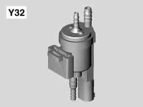
P14.30-2042-01
Y32 Umschaltventil Luftpumpe (Lufteinblasung)
Anordnung
Das Umschaltventil Luftpumpe ist vorn am rechten Zylinderkopf angeordnet.
Aufgabe
Das Umschaltventil Luftpumpe steuert die Luftabschaltventile mit Unterdruck aus dem Saugrohr an.
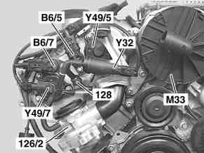
P07.61-3009-01
126/2 Abschaltventil Lufteinblasung rechts (Kombiventil: Rückschlagventil integriert)
128 Rückschlagventil (Unterdruck)
B6/5 Hall-Geber Einlass Nockenwelle, rechts
B6/7 Hall-Geber Auslass Nockenwelle, rechts
M33 Elektrische Luftpumpe
Y32 Umschaltventil Luftpumpe
Y49/5 Stellmagnet Einlass Nockenwelle, rechts
Y49/7 Stellmagnet Auslass Nockenwelle, rechts

P07.10-0308-81
1 Belüftung
2 Unterdruckversorgung vom Saugrohr
3 Anschluss zu den Luftabschaltventilen
a Ankerscheibe
b Rückstellfeder
c Gehäuse
d Elektromagnet (Spule)
e Elektrischer Anschluss
f Dichtgummi
Aufbau
Elektromagnetisches Umschaltventil, Spannungsversorgung von Klemme 87, Spulenwiederstand ca. 28 Ω.
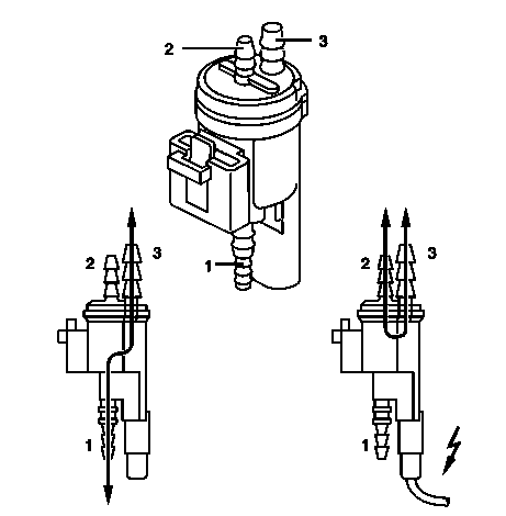
P14.30-0250-12
1 Belüftung
2 Unterdruckversorgung vom Saugrohr
3 Anschluss zu den Luftabschaltventilen
Funktion
Bei Ansteuerung wird die Ankerscheibe (a) vom Elektromagnet (d) angezogen und der Dichtgummi (f) verschließt die Belüftung. Die Verbindung zwischen Anschluss 2 und Anschluss 3 wird freigegeben. Somit wird der Unterdruck vom Saugrohr zu den Luftabschaltventilen aufgebaut. Im unbestromten Zustand wird die Verbindung zwischen Anschluss 1 und Anschluss 3 wieder hergestellt und Anschluss 3 wird somit belüftet.