20-0006 Coolant circuit diagrams and thermostat
Coolant circuit diagram T1

A | Bypass circuit up to 82 °C |
B | Radiator circuit above 94 °C |
C | Heater circuit |
1 | Overflow pipe |
2 | Cap |
3 | Radiator |
4 | Cylinder head |
5 | Crankcase |
6 | Heat exchanger |
7 | Coolant pump |
8 | Thermostat |
Coolant circuit diagram T2

A | Bypass circuit up to 82 °C |
B | Radiator circuit above 94 °C |
C | Heater circuit |
D | Overflow circuit |
1 | Overflow pipe |
2 | Cap |
3 | Expansion tank |
4 | Radiator |
5 | Cylinder head |
6 | Crankcase |
7 | Heat exchanger |
8 | Coolant pump |
9 | Thermostat |
Thermostat
Start of opening at °C | 802 |
Stroke in mm | 8 |
Fully open at °C | 94 |

Function of thermostat
-------------------------------
Coolant temperature up to approx. 82 °C:
The main valve is closed and the bypass plate is fully open.
The flow from the radiator is thus interrupted. The coolant flows along the bypass passage (X) through the coolant pump into the crankcase (Y).

Coolant temperature approx. 82 °C up to
94 °C:
The main valve and the bypass plate are open.
The coolant flows from the radiator (Z) and from the cylinder head along the bypass passage (X) through the coolant pump into the crankcase (Y).
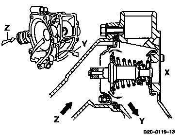
Coolant temperature above 94 °C:
The main valve is fully open and the bypass plate is closed.
All of the coolant flows from the radiator (Z) through the coolant pump into the crankcase (Y).

Note
The cooling system is automatically bled via the ball valve (arrow) in the thermostat when the system is filled.